New Blynk IOT Smart Plant Monitoring System
Summary
TLDRIn this tutorial, the creator unveils a smart plant monitoring system integrated with the Blink IoT platform, featuring real-time data access via a smartphone app and web dashboard. The project utilizes sensors like PIR motion, DHT11 for temperature and humidity, and a soil moisture sensor, controlled by an ESP8266 board. It also includes a relay module for a water pump and an LCD display for sensor readings. The video guides through the assembly, Blink IoT platform setup, and code uploading, showcasing a hands-on approach to home gardening tech.
Takeaways
- 🌟 The video is sponsored by LTM 365, a PCB designing tool, and Octopart, a search engine for electronic components.
- 🎉 The presenter wishes viewers a Happy New Year and introduces a smart plant monitoring system project.
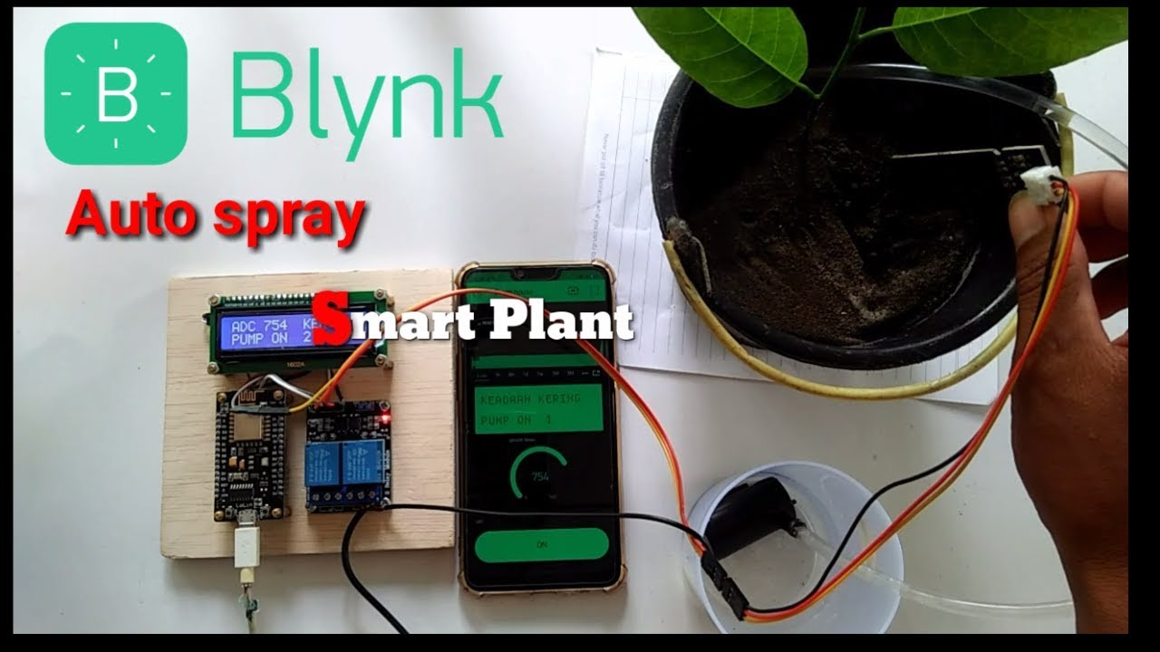
- 🌱 The smart plant monitoring system is an upgraded version that works with the Blink IoT platform and can be controlled via a smartphone app or web dashboard.
- 📱 The system includes sensors for PIR motion, temperature, humidity, and soil moisture, along with a relay module to control a water pump or DC motor.
- 💧 A 16x2 I2C LCD display is used to show real-time data from the sensors, including temperature, humidity, soil moisture, motion detection, and water pump status.
- 🔌 The project is powered by an ESP8266 board and includes a manual button for the water pump with real-time feedback on the application.
- 🛠️ The required components for the project are listed, including the ESP8266 board, sensors, a relay module, a display, a push button, a water pump, and a 7.4V 18650 battery.
- 🔗 Links for free trials of Altium Designer, LTM 365, and Octopart are provided in the video description for interested viewers.
- 🛑 The video demonstrates how to set up the project on the Blink IoT platform, including creating data streams, events, and configuring the web dashboard and mobile application.
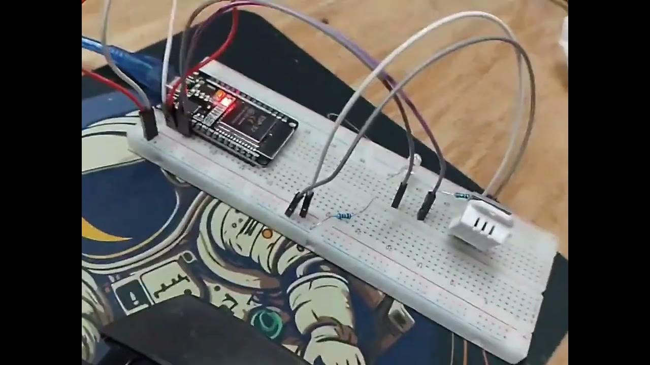
- 🔧 The presenter guides viewers through the process of connecting the sensors and components to the ESP8266 board according to a provided circuit diagram.
- 📲 The video concludes with a demonstration of the smart plant monitoring system in action, showing real-time data on the LCD display, mobile app, and web dashboard.
Q & A
What is the main focus of the video?
-The video focuses on demonstrating how to make a smart plant monitoring system that works with the Blink IoT platform.
What is the purpose of the PIR motion sensor in this project?
-The PIR motion sensor is used to detect any animal activity in the vicinity of the plant.
Which temperature and humidity sensor is used in the project?
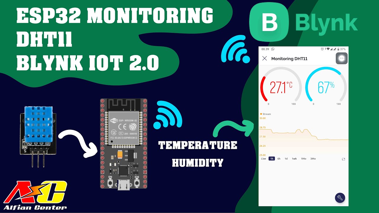
-A DHT11 temperature and humidity sensor is used in the smart plant monitoring system.
What does the soil moisture sensor do in the project?
-The soil moisture sensor is used to measure the moisture level in the soil to determine when the plant needs watering.
How is the water pump controlled in the project?
-A relay module is used to turn the water pump on and off, which is demonstrated with a DC motor in the project.
What display is used to show sensor values in the project?
-A 16x2 I2C LCD display is used to display values from the sensors, such as temperature, humidity, and soil moisture.
What platform does the smart plant monitoring system communicate with?
-The system communicates with the Blink IoT platform, allowing for real-time monitoring and control via smartphone and web dashboard.
How can viewers access the codes and circuit diagram for the project?
-The codes and circuit diagram can be downloaded from the website link provided in the video description.
What is the role of the push button in the project?
-The push button is used to manually turn the water pump on and off, providing real-time feedback on the application.
What is the significance of the Blink IoT application in the project?
-The Blink IoT application allows users to view real-time data from the sensors and control the water pump and PIR sensor remotely.
How does the project notify the user of motion detection?
-When motion is detected by the PIR sensor, the user receives a notification on their smartphone, and a red light glows on the application indicating motion.
Outlines

Dieser Bereich ist nur für Premium-Benutzer verfügbar. Bitte führen Sie ein Upgrade durch, um auf diesen Abschnitt zuzugreifen.
Upgrade durchführenMindmap

Dieser Bereich ist nur für Premium-Benutzer verfügbar. Bitte führen Sie ein Upgrade durch, um auf diesen Abschnitt zuzugreifen.
Upgrade durchführenKeywords

Dieser Bereich ist nur für Premium-Benutzer verfügbar. Bitte führen Sie ein Upgrade durch, um auf diesen Abschnitt zuzugreifen.
Upgrade durchführenHighlights

Dieser Bereich ist nur für Premium-Benutzer verfügbar. Bitte führen Sie ein Upgrade durch, um auf diesen Abschnitt zuzugreifen.
Upgrade durchführenTranscripts

Dieser Bereich ist nur für Premium-Benutzer verfügbar. Bitte führen Sie ein Upgrade durch, um auf diesen Abschnitt zuzugreifen.
Upgrade durchführenWeitere ähnliche Videos ansehen
Penyiraman tanaman otomatis berbasis IOT(Internet Of Things) graph chart blynk nodemcu esp8266
Monitoring Data Suhu dan Kelembapan Sensor DHT11 Menggunakan ESP32 dan BLYNK IOT 2.0

Menghubungkan ESP32 ke Blynk Full Tutorial
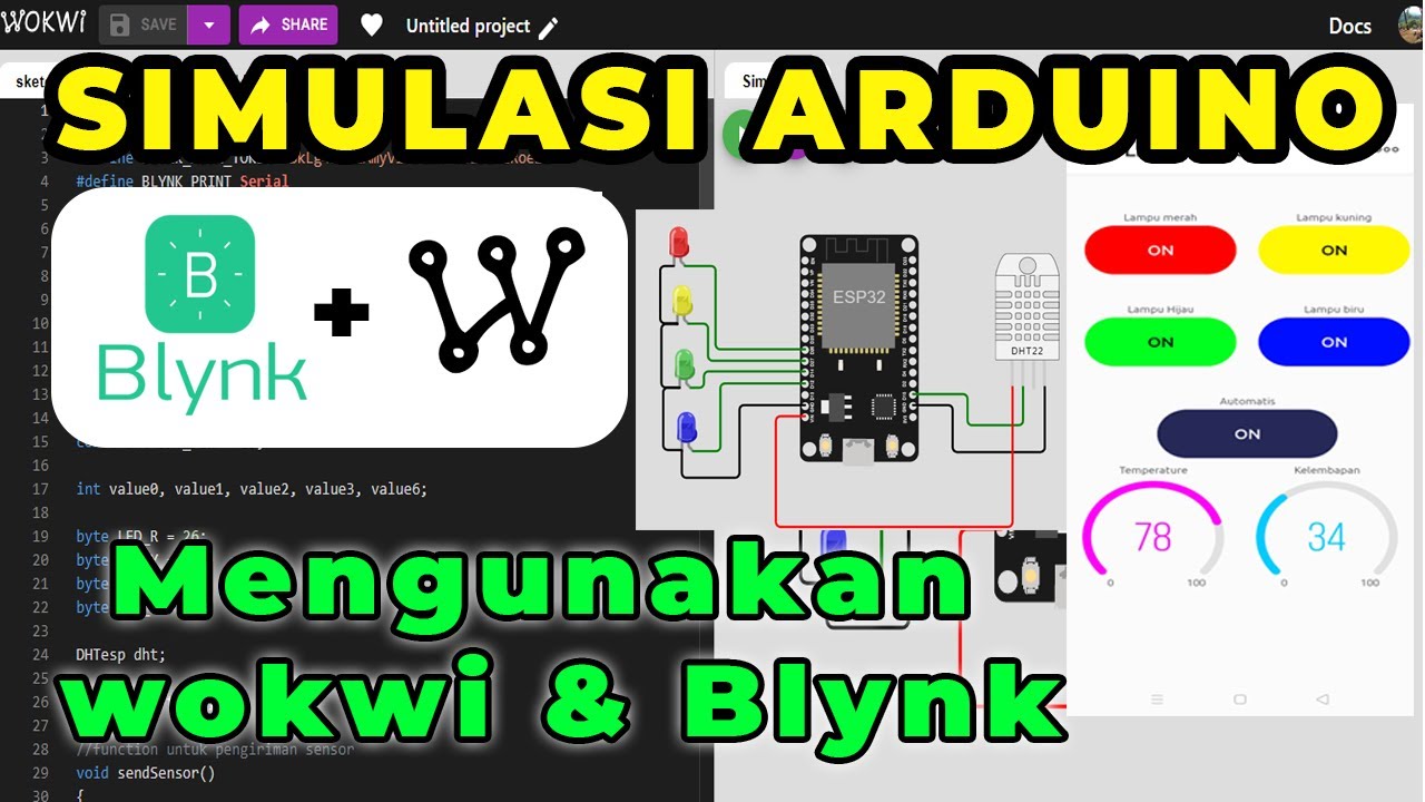
SIMULASI WOKWI MENGUANKAN BLYNK ARDUINO
penjelasan keterhubungan antara ESP32 dengan Blnyk web

Bertani Cerdas Dengan IoT, Perawatan Mandiri dari Smartphone Hemat Waktu dan Tenaga Kerja
5.0 / 5 (0 votes)
