Praktikum RANGKAIAN RLC SERI PADA ARUS AC menggunakan Virtual Lab PHET.
Summary
TLDRThis video provides a step-by-step guide for assembling an RLC circuit in a virtual environment, aimed at practicing AC circuit construction. The process involves selecting components such as resistors, inductors, and capacitors, setting control variables like voltage and frequency, and using instruments like voltmeters and ammeters to measure voltage and current. The user adjusts component values and gathers data to analyze circuit behavior. The video emphasizes practical learning, including graphing the relationship between impedance, inductance, and capacitive reactance, helping viewers understand RLC circuits and their dynamic properties.
Takeaways
- 😀 Set up a virtual AC circuit using a resistor, inductor, capacitor, and voltage source.
- 😀 Use the AC voltage source to power the circuit and set the voltage to 9V.
- 😀 Adjust the frequency of the AC voltage to 0.5Hz as a control variable.
- 😀 Change resistor values (e.g., 10Ω, 12Ω, 14Ω) to observe their effect on the circuit.
- 😀 Modify the inductor value (e.g., 5H to 5.25H) to test different inductance levels.
- 😀 Alter the capacitor's capacitance (e.g., 0.1µF to 0.2µF) for varied results.
- 😀 Measure effective voltage using a voltmeter and effective current with an ammeter.
- 😀 Ensure that the voltmeter reads around 9V and the ammeter reads 0.53A as effective values.
- 😀 Record data in a table, noting the effective voltage, current, and impedance values.
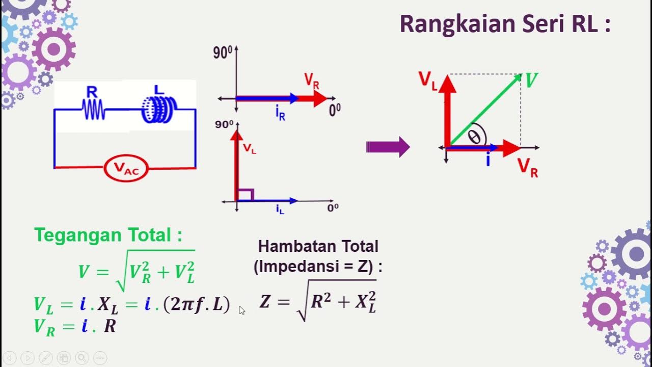
- 😀 Use the formula for impedance (Z) to analyze how resistance, inductive reactance, and capacitive reactance affect the circuit.
- 😀 Plot graphs based on the data to visualize how changes in components impact impedance and circuit behavior.
Q & A
What is the first step in constructing the AC circuit in the virtual environment?
-The first step is to select the 'Electric Magnet' menu, and then choose the 'AC Circuit Construction' option to load the circuit environment.
What are the three AC construction kit options presented after selecting the AC circuit menu?
-The three options presented are 'AC Voltage,' 'Reactance,' and 'RLC' circuit. The RLC circuit is selected for this particular practice.
Which components are used to build the series AC circuit in the virtual setup?
-The components used are a source (AC voltage), a cable, a resistor, an inductor, and a capacitor, all connected in series.
What is the control variable used to adjust the AC circuit in the practice?
-The control variables in the practice are the AC voltage and frequency, with the voltage set to a maximum of 9 volts and frequency adjusted to 0.5 Hz.
How can the resistor, inductor, and capacitor values be changed in the virtual setup?
-The resistor value can be adjusted between 10 and 14 ohms, the inductor value can be modified from 5 Henry, and the capacitor can be set from 0.1 farad to 0.2 farad.
What measuring instruments are used to evaluate the AC circuit?
-A voltmeter is used to measure the voltage, and an ammeter is used to measure the current in the circuit.
What is the significance of measuring 'effective' voltage and current?
-The 'effective' voltage and current represent the real power that can be measured by the instruments, and they are crucial in understanding the performance of the AC circuit.
How can the effective current be found in the circuit?
-The effective current can be determined using the ammeter, ensuring the readings match the expected values for the current in the circuit.
What is the purpose of the data table provided in the practical activity?
-The data table is used to record the effective current, effective voltage, impedance (Z), and other circuit properties for analysis.
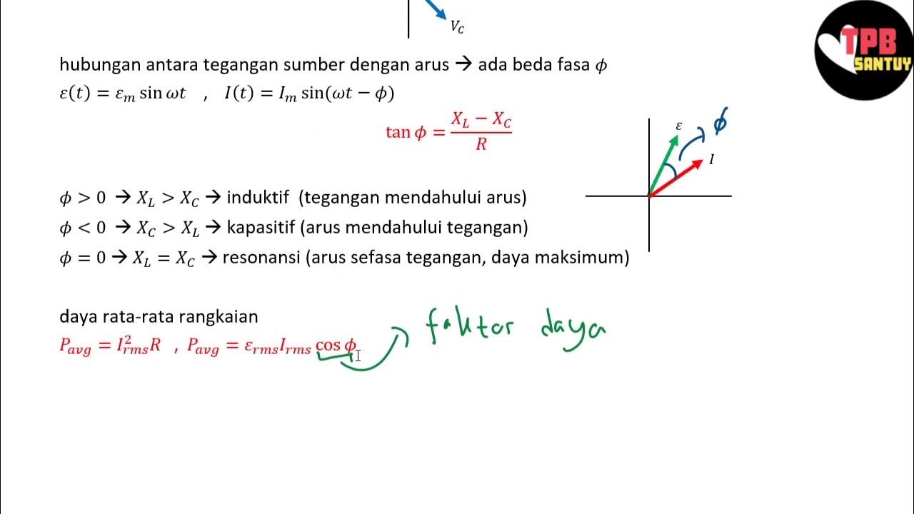
What is the relationship between inductive reactance (XL) and capacitive reactance (XC) in the circuit?
-When the inductive reactance (XL) exceeds the capacitive reactance (XC), the circuit becomes inductive, which influences the behavior of the AC circuit.
Outlines

Dieser Bereich ist nur für Premium-Benutzer verfügbar. Bitte führen Sie ein Upgrade durch, um auf diesen Abschnitt zuzugreifen.
Upgrade durchführenMindmap

Dieser Bereich ist nur für Premium-Benutzer verfügbar. Bitte führen Sie ein Upgrade durch, um auf diesen Abschnitt zuzugreifen.
Upgrade durchführenKeywords

Dieser Bereich ist nur für Premium-Benutzer verfügbar. Bitte führen Sie ein Upgrade durch, um auf diesen Abschnitt zuzugreifen.
Upgrade durchführenHighlights

Dieser Bereich ist nur für Premium-Benutzer verfügbar. Bitte führen Sie ein Upgrade durch, um auf diesen Abschnitt zuzugreifen.
Upgrade durchführenTranscripts

Dieser Bereich ist nur für Premium-Benutzer verfügbar. Bitte führen Sie ein Upgrade durch, um auf diesen Abschnitt zuzugreifen.
Upgrade durchführenWeitere ähnliche Videos ansehen
Rangkaian Seri RLC | Rangkaian AC | Part 2 | Fisika Dasar
Rangkaian Seri RL-RC-LC dengan Sumber AC

How to Make a Mosquito Killer Machine | AC Mosquito Killer Machine | Powerful Mosquito Killer

LTspice simulation | Examples in LTspice | RC Circuits | SPICE simulation

Montagem de QDC com DPS e IDR

How To Make A Mobile Phone Detector
5.0 / 5 (0 votes)
