Orthographic Projection from isometric view in Engineering drawing
Summary
TLDRThis video tutorial explains how to create orthographic projections from an isometric view in engineering drawing. It introduces the concepts of first and third angle projection methods, guiding viewers through the process of representing 3D objects on 2D planes. The tutorial details how to draw the front, top, and side views based on provided dimensions and projection lines. Emphasis is placed on accurate alignment and the importance of using reference lines to ensure precision in each view. This step-by-step guide is perfect for beginners learning technical drawing and orthographic projection techniques.
Takeaways
- 😀 Orthographic projection is a method used to represent 3D objects in 2D by showing various views (front, side, top).
- 😀 The two main types of projection methods are the first angle and third angle projection.
- 😀 In orthographic projection, it is important to follow standard projection rules to place views accurately on the planes.
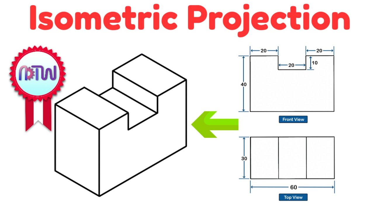
- 😀 The front view is drawn by imagining the object from the front, based on provided dimensions (length, height, width).
- 😀 The top view is drawn by projecting lines from the front view to create the shape of the object when viewed from above.
- 😀 The side view is drawn by projecting lines from both the front and top views, showing the object from the left side.
- 😀 To start drawing, draw a reference line (XY line) that will act as the base for all projections.
- 😀 The front view is placed above the XY line, the top view below, and the side view on the right if using the first angle projection method.
- 😀 Dimensions from the isometric view are essential for accurately drawing the front, top, and side views in orthographic projection.
- 😀 It's crucial to draw projection lines from the previous views to ensure proper alignment when creating each orthographic view.
Q & A
What is orthographic projection in engineering drawing?
-Orthographic projection is a method used to represent 3D objects on 2D planes by showing multiple views such as the front view, top view, and side view.
What are the two common methods of projection used in orthographic drawing?
-The two common methods are the first angle projection and the third angle projection.
How do the first angle and third angle projection methods differ?
-In the first angle method, the views are placed with the front view at the top, the top view below, and the side view on the right. In the third angle method, the views are placed with the front view at the bottom, the top view above, and the side view on the left.
What is an isometric view, and how does it relate to orthographic projections?
-An isometric view is a graphical representation of a 3D object, where all three axes are equally scaled. Orthographic projection converts this 3D view into 2D views like the front, top, and side views.
What should be done first when starting an orthographic projection drawing?
-The first step is to draw the reference line (XY line) that will guide the placement of the different views on the drawing.
How do you draw the front view in an orthographic projection?
-To draw the front view, start by determining the dimensions such as length, height, and width, then draw a rectangle with those measurements and divide it as required by the object's design.
How is the top view different from the front view in orthographic projection?
-The top view shows the object from above, and its dimensions may differ from the front view. Projection lines from the front view are used to position the top view on the drawing.
How do you draw the side view in an orthographic projection?
-To draw the side view, use projection lines from both the front and top views. Include dimensions like height and width and represent the shape using rectangles and lines accordingly.
What role do projection lines play in orthographic projections?
-Projection lines help transfer the dimensions and features from one view to another, ensuring accurate placement of the views on the drawing.
What are dotted lines used for in the side view of an orthographic projection?
-Dotted lines in the side view represent intersections and hidden parts of the object that are not directly visible in that view.
Outlines

Dieser Bereich ist nur für Premium-Benutzer verfügbar. Bitte führen Sie ein Upgrade durch, um auf diesen Abschnitt zuzugreifen.
Upgrade durchführenMindmap

Dieser Bereich ist nur für Premium-Benutzer verfügbar. Bitte führen Sie ein Upgrade durch, um auf diesen Abschnitt zuzugreifen.
Upgrade durchführenKeywords

Dieser Bereich ist nur für Premium-Benutzer verfügbar. Bitte führen Sie ein Upgrade durch, um auf diesen Abschnitt zuzugreifen.
Upgrade durchführenHighlights

Dieser Bereich ist nur für Premium-Benutzer verfügbar. Bitte führen Sie ein Upgrade durch, um auf diesen Abschnitt zuzugreifen.
Upgrade durchführenTranscripts

Dieser Bereich ist nur für Premium-Benutzer verfügbar. Bitte führen Sie ein Upgrade durch, um auf diesen Abschnitt zuzugreifen.
Upgrade durchführenWeitere ähnliche Videos ansehen

Isometric View | How to Construct an Isometric View of an Object
Isometric Projection in Engineering Drawing | isometric projection 3D from orthographic view

Exercise 1.1 Orthographic Drawing

ORTHOGRAPHIC DRAWING EXAMPLE

Orthographic Projection_An Introduction_Engineering Drawing_Engineering Graphics_English

ENGINEERING DRAWING DOUBTS SESSION 1 | ENGINEERING GRAPHICS COMMENTS REPLY 1
5.0 / 5 (0 votes)
