How to Program PLC Using Ladder Diagram | RSLogix
Summary
TLDRThis tutorial demonstrates the basics of using RSLogix Micro 500 and RSLogix Emulate 500 to design and simulate ladder logic diagrams for controlling PLC processes. It covers key concepts like programming AND, OR, and NOT gates, setting up I/O modules, and verifying logic. The video also shows how to simulate button presses to test start/stop motor functions and control lights using a PLC system. The practical demonstration helps learners understand the importance of testing ladder logic in a virtual environment before applying it to real-world systems.
Takeaways
- 😀 **Introduction to RSLogix Micro Simulator**: The video demonstrates how to use the RSLogix software and RSLogix Micro Simulator to implement and test ladder logic diagrams for PLCs.
- 😀 **Setting Up the Environment**: Learners are guided through the steps of setting up the RSLogix and RS Links software, with emphasis on creating and configuring a new project for PLC simulation.
- 😀 **Understanding I/O Configuration**: The video explains how to configure input and output ports in RSLogix, with the MicroLogix 1100 Series PLC as an example. The significance of I/O addressing is clarified.
- 😀 **Creating Ladder Logic**: The tutorial walks through building simple ladder logic diagrams, such as AND, OR, and NOT gates, with clear instructions on assigning appropriate input/output addresses.
- 😀 **Practical Example of Motor and Light Control**: The tutorial illustrates how to control a motor and lights using a start button, stop button, and a latching circuit, which helps to simulate real-world control systems.
- 😀 **Testing Ladder Logic**: After creating the ladder logic, learners are shown how to test it by toggling inputs and observing the outputs in the RSLogix Emulator to verify proper functionality.
- 😀 **Explanation of Latching Function**: The latching function is demonstrated, where the motor stays on even if the start button is released, highlighting the importance of maintaining state in PLC systems.
- 😀 **Stop Button Functionality**: The video also covers the stop button functionality, where activating it turns the motor off and triggers the light off indicator, showcasing basic control logic.
- 😀 **Simulating Real-World Scenarios**: By controlling lights and motors, the video simulates a common industrial control system, allowing learners to understand how PLCs can be used in practical applications.
- 😀 **Emphasis on Hands-on Practice**: Viewers are encouraged to practice their newly learned skills by creating and testing additional ladder logic diagrams, reinforcing their understanding of PLC programming.
Q & A
What is the purpose of using the RSLogix Micro Simulator in this tutorial?
-The RSLogix Micro Simulator is used in this tutorial to simulate and test PLC ladder logic diagrams, allowing learners to practice programming without needing physical hardware.
What steps are involved in setting up the RSLogix Micro Simulator software?
-The steps include launching RSLinks to connect the PLC emulator, opening RSLogix Micro Starter, creating a new project, and selecting the appropriate PLC model (e.g., MicroLogix 1100).
What are the input and output ranges for a typical MicroLogix 1100 PLC in RSLogix?
-The input range is from `I:0/0` to `I:0/95`, which represents 96 input points. The output range is from `O:0/0` to `O:0/63`, representing 64 output points.
How do you create a basic AND gate in ladder logic using RSLogix?
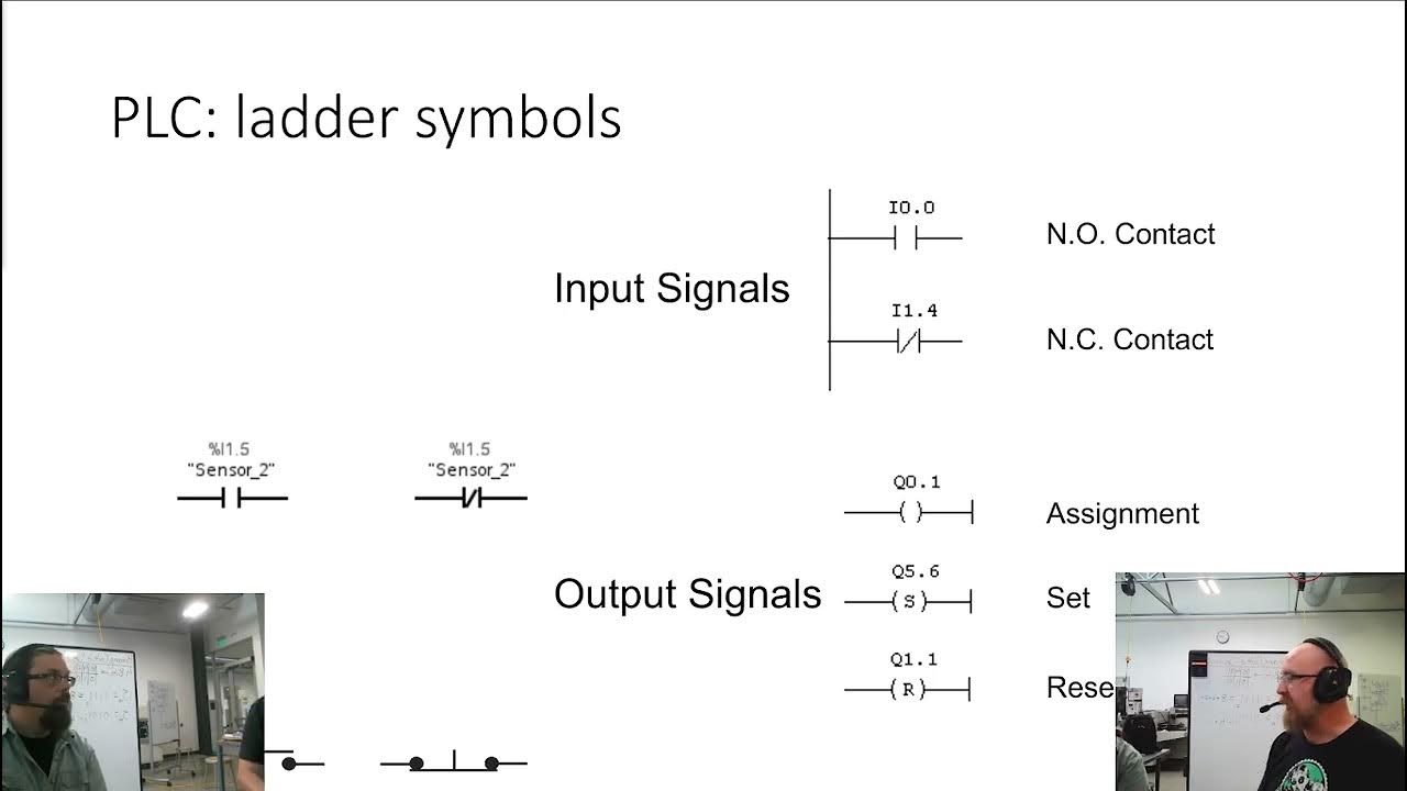
-A basic AND gate is created by connecting two normally open switches in series. Both inputs must be high for the output to be activated. The output is mapped to a specific address in the ladder logic.
What is the function of the OR gate in ladder logic, and how is it implemented?
-The OR gate in ladder logic is implemented by placing two normally open switches in parallel. The output will turn on if either of the switches is activated, meaning either input can trigger the output.
How does a NOT gate work in ladder logic, and how is it represented?
-A NOT gate is implemented by using a normally closed switch. When the input is high, the output will be low, and vice versa, effectively inverting the input signal.
What does the Verify function do in RSLogix, and why is it important?
-The Verify function checks the ladder logic for errors, ensuring that the program is free of syntax or configuration issues before running the simulation.
What is the purpose of toggling input bits in the RSLogix Simulator?
-Toggling input bits simulates pressing or releasing physical buttons (like Start or Stop), allowing you to test the logic’s response to changes in input conditions.
What happens when the Start button is pressed in the simulation, and how is this shown in the lights?
-When the Start button is pressed, the motor turns on, and the 'light off' light goes off. Simultaneously, the 'light on' light turns on to indicate that the motor is running.
What is the role of the Latching function in PLC ladder logic, and how is it demonstrated in this tutorial?
-The Latching function ensures that the motor stays on even after releasing the Start button. The motor remains activated until the Stop button is pressed, which simulates real-world behavior in automation.
Outlines

Dieser Bereich ist nur für Premium-Benutzer verfügbar. Bitte führen Sie ein Upgrade durch, um auf diesen Abschnitt zuzugreifen.
Upgrade durchführenMindmap

Dieser Bereich ist nur für Premium-Benutzer verfügbar. Bitte führen Sie ein Upgrade durch, um auf diesen Abschnitt zuzugreifen.
Upgrade durchführenKeywords

Dieser Bereich ist nur für Premium-Benutzer verfügbar. Bitte führen Sie ein Upgrade durch, um auf diesen Abschnitt zuzugreifen.
Upgrade durchführenHighlights

Dieser Bereich ist nur für Premium-Benutzer verfügbar. Bitte führen Sie ein Upgrade durch, um auf diesen Abschnitt zuzugreifen.
Upgrade durchführenTranscripts

Dieser Bereich ist nur für Premium-Benutzer verfügbar. Bitte führen Sie ein Upgrade durch, um auf diesen Abschnitt zuzugreifen.
Upgrade durchführenWeitere ähnliche Videos ansehen
5.0 / 5 (0 votes)


