Router on a Stick Inter-VLAN Routing | CISCO Certification
Summary
TLDRThis video guides viewers through the configuration of Router on a Stick for Inter-VLAN Routing. It covers the setup of multiple VLANs across switches, assigns IP addresses to PCs, and demonstrates how to enable communication between VLANs using sub-interfaces on a router. The video details the creation of VLANs on switches, configuring trunking between switches, and routing between VLANs using dot1Q encapsulation. Troubleshooting steps for successful inter-VLAN communication are also discussed. The video provides a thorough walkthrough of network configuration and verification, offering insights into setting up a router to handle traffic between isolated VLANs.
Takeaways
- 😀 The video explains how to configure Router-on-a-Stick (ROAS) for inter-VLAN routing using a router and multiple switches.
- 😀 VLANs are created on the switches for different networks (VLAN 10 for Students, VLAN 20 for Faculty, and VLAN 30 for Guests).
- 😀 Each switch port is assigned to the appropriate VLAN (e.g., FastEthernet0/1 is assigned to VLAN 10).
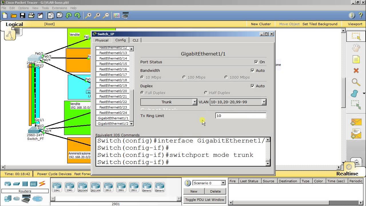
- 😀 Trunking is enabled between switches to allow multiple VLAN traffic to pass through the same link.
- 😀 Sub-interfaces are configured on the router to facilitate inter-VLAN routing (e.g., g0/0.10 for VLAN 10).
- 😀 IP addressing is assigned to each VLAN, with a specific network address for each (e.g., 192.168.10.0/24 for VLAN 10).
- 😀 Devices in the same VLAN can successfully communicate, but inter-VLAN communication fails without proper routing configuration.
- 😀 VLANs are configured with dot1Q encapsulation for VLAN tagging, allowing them to be recognized across trunk links.
- 😀 Router’s physical interface (g0/0) must be enabled for sub-interfaces to function properly.
- 😀 Connectivity between different VLANs is tested using pings, and failures in communication are diagnosed by checking VLAN and trunk configurations.
- 😀 The router's sub-interface configuration includes specifying the correct IP address and VLAN ID for routing between VLANs (e.g., 192.168.10.1/24 for VLAN 10).
Q & A
What is the purpose of configuring Router on a Stick for inter-VLAN routing?
-Router on a Stick is configured for inter-VLAN routing to enable communication between different VLANs using a single physical router interface, with sub-interfaces for each VLAN.
Which router model and switches are used in the configuration?
-The configuration uses a router model of 1941 and three switches, along with several connected PCs.
How are the VLANs created and assigned on the switches?
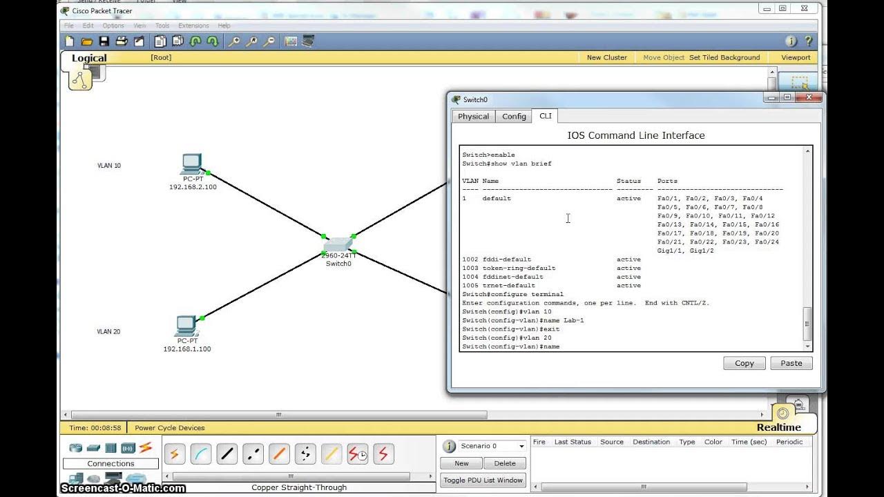
-VLANs 10, 20, and 30 are created on each switch using the 'vlan' command in the terminal, and ports are assigned to the appropriate VLANs using the 'switchport access vlan' command.
What IP address ranges are used for the different VLANs?
-The IP address ranges used are: VLAN 10: 192.168.10.0/24, VLAN 20: 192.168.20.0/24, and VLAN 30: 192.168.30.0/24.
What is the purpose of setting a default gateway for the PCs?
-The default gateway is set on the PCs to allow them to communicate with devices outside their local subnet, such as devices in other VLANs.
How do you configure a router's sub-interfaces for VLANs?
-Sub-interfaces are configured by creating an interface for each VLAN (e.g., g0/0.10 for VLAN 10) and applying dot1q encapsulation, followed by assigning an IP address for the VLAN's network.
What is the role of trunk ports in the configuration?
-Trunk ports are configured on the switches to allow multiple VLAN traffic to pass between the router and switches, using dot1q encapsulation to separate the VLANs.
What command is used to verify that VLANs have been created on the switches?
-The 'show vlan brief' command is used to verify that the VLANs have been created on the switches.
What troubleshooting steps should be taken if VLAN-to-VLAN communication fails?
-If VLAN-to-VLAN communication fails, check the trunk configuration, ensure sub-interfaces on the router are up, and verify that VLANs are properly assigned to ports on the switches.
What happens if the router interface connected to the switches is administratively down?
-If the router interface is administratively down, the sub-interfaces for inter-VLAN routing will also be down, causing a failure in communication between VLANs.
Outlines

Dieser Bereich ist nur für Premium-Benutzer verfügbar. Bitte führen Sie ein Upgrade durch, um auf diesen Abschnitt zuzugreifen.
Upgrade durchführenMindmap

Dieser Bereich ist nur für Premium-Benutzer verfügbar. Bitte führen Sie ein Upgrade durch, um auf diesen Abschnitt zuzugreifen.
Upgrade durchführenKeywords

Dieser Bereich ist nur für Premium-Benutzer verfügbar. Bitte führen Sie ein Upgrade durch, um auf diesen Abschnitt zuzugreifen.
Upgrade durchführenHighlights

Dieser Bereich ist nur für Premium-Benutzer verfügbar. Bitte führen Sie ein Upgrade durch, um auf diesen Abschnitt zuzugreifen.
Upgrade durchführenTranscripts

Dieser Bereich ist nur für Premium-Benutzer verfügbar. Bitte führen Sie ein Upgrade durch, um auf diesen Abschnitt zuzugreifen.
Upgrade durchführenWeitere ähnliche Videos ansehen

Types of Inter VLAN Routing & Basic Inter VLAN Routing Configuration | (VLAN PART 4)

Konfigurasi VLAN di Cisco Packet Tracer

Aula 04 - Curso de Redes de Computadores Básico Mão na Massa - Gateway e Interface Vlan

Single Switch VLAN in Packet Tracer

Konfigurasi Inter Vlan Routing pada Cisco packet tracer (Routing on a Stick)

VLAN trunking
5.0 / 5 (0 votes)
