Input and Output Addressing in Siemens PLC - Tia Portal Tutorial
Summary
TLDRToday's lecture covers input/output and memory addressing in Siemens PLCs. It explains the basics of digital and analog I/O, memory storage units like bits, bytes, words, and double words, and data types including Boolean, string, integer, and float. The lecture distinguishes between digital (Boolean) and analog (integer/float) signal addressing. It also details how PLCs convert sensor signals into machine-readable data, using signed and unsigned integers. The addressing format for digital and analog I/O in PLCs is discussed, highlighting identifiers like 'I' for inputs, 'Q' for outputs, and 'W' for analog word addressing.
Takeaways
- 💡 Digital inputs and outputs are categorized as digital signals, while analog inputs and outputs correspond to analog signals.
- 📊 Data in Siemens PLC is stored in bits (zeros and ones), and various units such as byte (8 bits), word (16 bits), and double word (32 bits) are used for memory addressing.
- 🔢 There are four main data types in PLC programming: boolean (0 or 1), string (characters), integer (both positive and negative values), and float (decimal values).
- 📉 Boolean data types are used for digital signals, while integer and float data types are used for analog signals.
- 🎛️ Addressing is divided into two categories: I/O addressing for input/output terminals and memory addressing for internal memory of the PLC.
- ⚙️ Unsigned integers only store positive values, while signed integers include both positive and negative values, determined by the presence of a sign before the value.
- 🧮 The number of possible states using bits is calculated as 2^n, where n is the number of bits. For example, 2 bits give 4 states, 8 bits give 256 states.
- 🔢 In Siemens PLCs, I/O addressing for inputs uses the 'I' identifier, and output addressing uses the 'Q' identifier.
- 🧾 Analog inputs and outputs use word addressing, which consists of 16 bits to handle the data (e.g., IW for input word, QW for output word).
- 🔄 Digital inputs and outputs increment the address after 8 bits (from 0 to 7), while analog addresses update in steps of 2 (IW 128, IW 130).
Q & A
What are the two main categories of inputs and outputs in Siemens PLCs?
-The two main categories of inputs and outputs in Siemens PLCs are digital inputs/outputs and analog inputs/outputs.
What is a bit, and how does it relate to a byte and a word?
-A bit is the smallest unit of data and represents either 0 or 1. A byte is a combination of 8 bits, and a word is a combination of 2 bytes or 16 bits.
What are the four main data types used in PLC programming?
-The four main data types used in PLC programming are boolean, string, integer, and float. Boolean represents digital signals (0 or 1), strings represent characters, integers represent whole numbers, and floats represent decimal values.
What is the difference between signed and unsigned integers?
-Unsigned integers only represent non-negative values (0 and above), while signed integers can represent both positive and negative values by including a sign before the value.
How many states can be represented using 2 bits?
-Using 2 bits, 4 states can be represented, which are 00, 01, 10, and 11.
What is the range of values that can be represented using 8 bits for signed and unsigned integers?
-For unsigned integers, 8 bits can represent values from 0 to 255. For signed integers, the range is from -128 to +127.
What is the function of IO addressing in a PLC?
-IO addressing in a PLC is used to address the input and output terminals, allowing the PLC to manage the signals from and to sensors and actuators.
What do the identifiers 'I' and 'Q' represent in Siemens PLC addressing?
-'I' represents input addressing, while 'Q' represents output addressing in Siemens PLCs.
What does 'W' represent in Siemens PLC addressing for analog signals?
-'W' represents word addressing, which is used for analog inputs and outputs in Siemens PLCs, where data is usually represented in 16 bits.
How does the PLC convert analog signals such as current or voltage into data that the processor can understand?
-The PLC converts analog signals like 4-20mA or 0-10V into digital data by converting the signals into binary form, which the processor can then interpret as integer or float values.
Outlines

Dieser Bereich ist nur für Premium-Benutzer verfügbar. Bitte führen Sie ein Upgrade durch, um auf diesen Abschnitt zuzugreifen.
Upgrade durchführenMindmap

Dieser Bereich ist nur für Premium-Benutzer verfügbar. Bitte führen Sie ein Upgrade durch, um auf diesen Abschnitt zuzugreifen.
Upgrade durchführenKeywords

Dieser Bereich ist nur für Premium-Benutzer verfügbar. Bitte führen Sie ein Upgrade durch, um auf diesen Abschnitt zuzugreifen.
Upgrade durchführenHighlights

Dieser Bereich ist nur für Premium-Benutzer verfügbar. Bitte führen Sie ein Upgrade durch, um auf diesen Abschnitt zuzugreifen.
Upgrade durchführenTranscripts

Dieser Bereich ist nur für Premium-Benutzer verfügbar. Bitte führen Sie ein Upgrade durch, um auf diesen Abschnitt zuzugreifen.
Upgrade durchführenWeitere ähnliche Videos ansehen

Truyền thông PROFINET S7-1200/1500 với nhiều PLC và thiết bị các hãng khác nhau thành 1 dây chuyền.

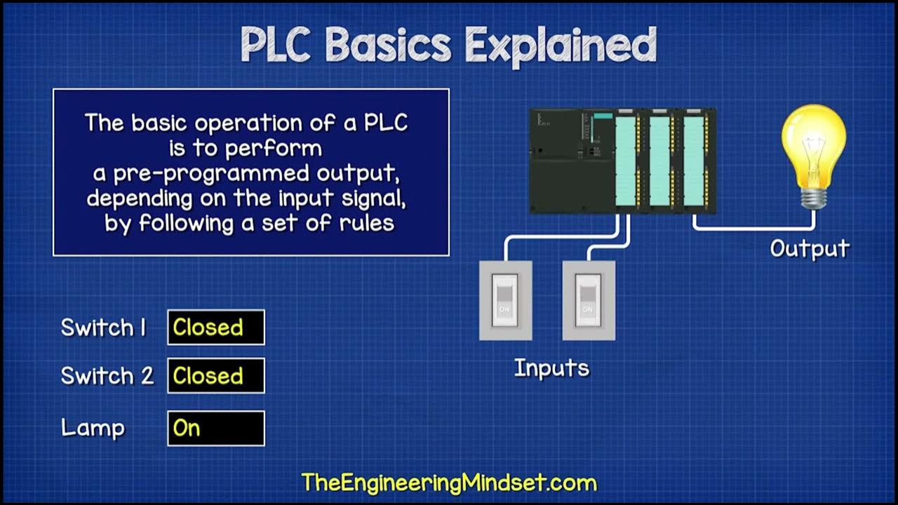
Nozioni base sui PLC ( Controllore Logico Programmabile)
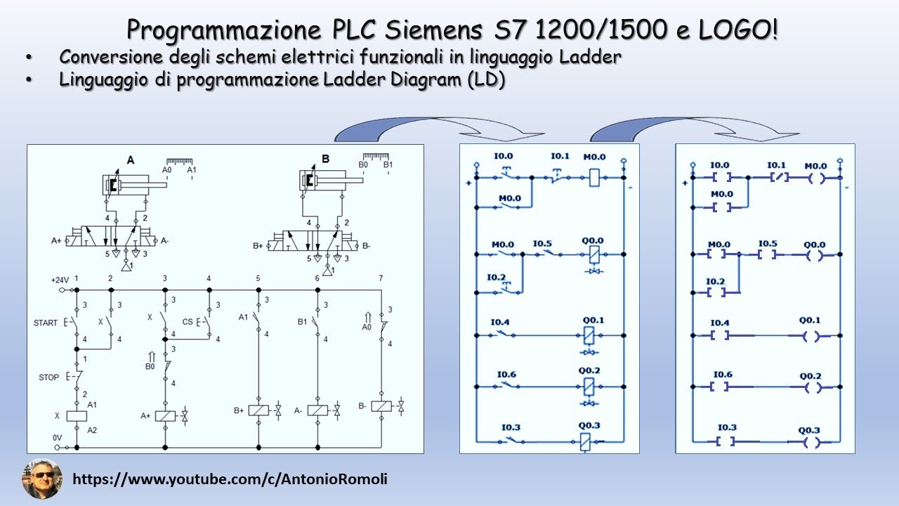
PLC: convertire lo schema elettrico funzionale in linguaggio di programmazione Ladder (Video 1.1)
SysAp 7 1 Ladder Logic
1. Berkenalan Dengan Kerja Perangkat Kontrol PLC
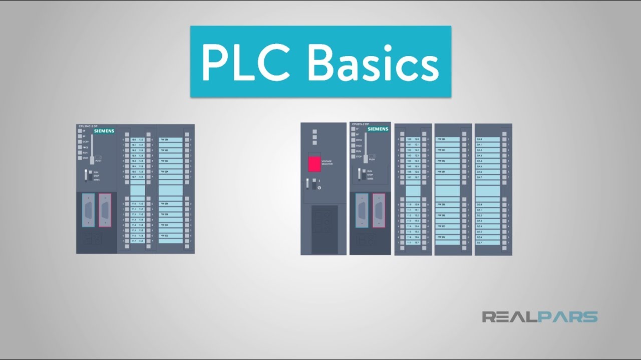
PLC Basics | Programmable Logic Controller
5.0 / 5 (0 votes)
