Understanding Stresses in Beams
Summary
TLDRThis video script explains the mechanics of beams under load, focusing on bending and shear stresses. It describes how a beam deforms, creating shear force and bending moments, and introduces pure bending scenarios. The script delves into calculating bending stresses using Hooke's law and the flexure formula, emphasizing the section modulus. It also covers shear stresses, their distribution, and maximum values, especially near the neutral axis. The video concludes with a discussion on shear stress in different beam cross-sections, including I-beams and circular sections.
Takeaways
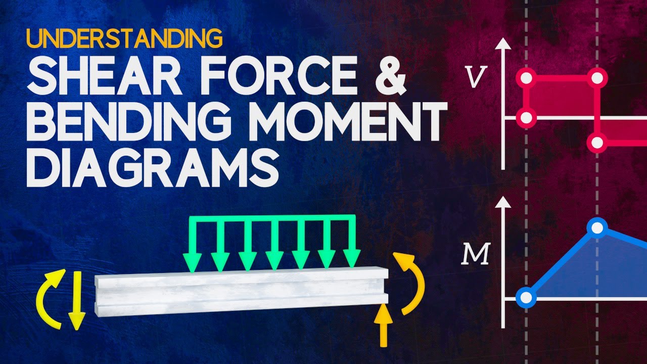
- 😌 When a load is applied to a beam, it bends, generating internal stresses in the form of shear force and bending moment.
- 🔍 Shear force is the resultant of vertical shear stresses acting parallel to the cross-section, while bending moment is due to normal stresses acting perpendicularly.
- 📐 Understanding these stresses is crucial for designing and analyzing beams, as they help in calculating the forces involved.
- 🌉 In pure bending, the shear force is zero, and there is a constant bending moment along the beam's length.
- 📉 Bending stresses develop as the beam deflects, with fibers at the top in compression and those at the bottom in tension.
- 🔄 The neutral surface is where fibers remain the same length during bending, passing through the centroid of the cross-section.
- 📏 Bending strain can be calculated using the geometry of deformation, considering the arc formed by fibers during bending.
- 📐 Hooke's law can be applied to calculate bending stress if stresses remain within the elastic region.
- 📉 The flexure formula relates bending stress to the bending moment, distance from the neutral axis, and area moment of inertia.
- 🔑 The section modulus (I/Y-max) is a key parameter indicating the resistance to bending and is often listed for common beam cross-sections.
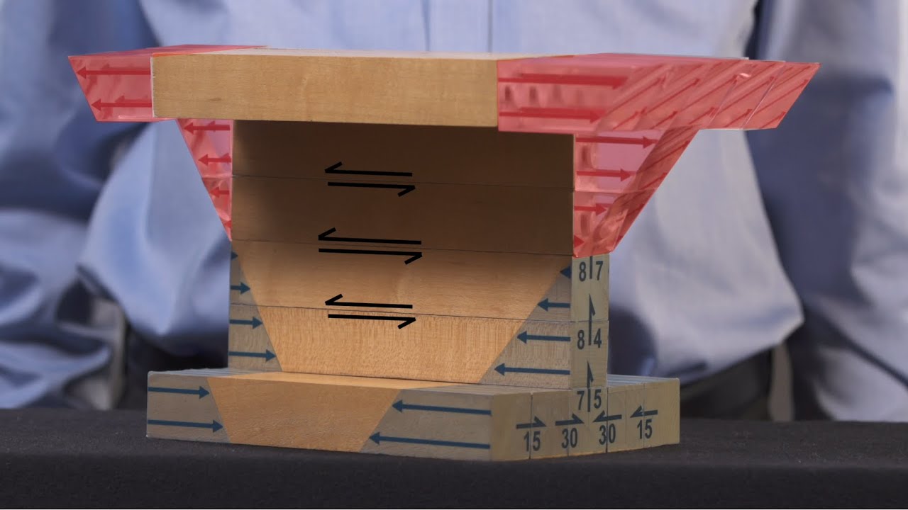
- 🔄 Shear force is the resultant of shear stresses acting vertically and parallel to the cross-section.
- 📊 Shear stress is not uniformly distributed across the beam's cross-section and is maximum at the neutral axis.
Q & A
What happens to a beam when it is subjected to a load?
-When a beam is subjected to a load, it deforms by bending, generating internal stresses represented by a shear force and a bending moment.
What is the difference between shear force and bending moment?
-Shear force is the resultant of vertical shear stresses acting parallel to the cross-section, while the bending moment is the resultant of normal stresses, called bending stresses, acting perpendicular to the cross-section.
Why is it important to understand bending and shear stresses in beams?
-Understanding these stresses is crucial as any design or analysis of a beam will involve calculating them to ensure structural integrity and performance.
What is pure bending and how is it defined?
-Pure bending occurs when the shear force along a section of a beam is equal to zero, resulting in a constant bending moment along its length.
How does a beam deflect under a constant bending moment?
-Under a constant bending moment, the beam deflects and the fibers at the top of the beam get shorter (in compression), while those at the bottom get longer (in tension).
What is the neutral surface in a beam?
-The neutral surface is a surface within the beam containing fibers that remain the same length during deformation, passing through the centroid of the cross-section.
How can bending strain in a beam be calculated?
-Bending strain can be calculated by considering the geometry of the deformation and the change in length of fibers relative to their original length.
What is Hooke's law and how is it applied to calculate bending stresses?
-Hooke's law for uniaxial stress states that stress is proportional to strain within the elastic region. It is applied to calculate bending stresses using the equation derived from the radius of curvature of the deformation.
What is the flexure formula and what does it tell us?
-The flexure formula relates bending stress to the bending moment, distance from the neutral axis, and the area moment of inertia. It shows that bending stress increases with bending moment and distance from the neutral axis, and decreases with an increase in the area moment of inertia.
What is the section modulus and why is it important?
-The section modulus is a measure of a cross-section's resistance to bending, defined as the ratio of the area moment of inertia to the distance from the neutral axis to the outermost fiber. It is important for determining the maximum bending stress in a beam.
How does the presence of a shear force affect bending stresses?
-The presence of a shear force does not significantly affect bending stresses, so the flexure formula derived for pure bending can be used for more general cases of bending.
How are shear stresses distributed across a beam's cross-section?
-Shear stresses are not uniformly distributed across a beam's cross-section; they are zero at the free surfaces and increase parabolically towards the neutral axis, where they reach a maximum.
What assumptions are made in the equation for calculating shear stress at the neutral axis?
-The equation assumes that shear stresses are constant across the width of the cross-section and aligned with the Y axis, which is reasonable for thin rectangular cross-sections.
How can the shear stress in a thin-walled section like an I-beam be estimated?
-In an I-beam, the web carries most of the shear force, and the shear stresses are distributed evenly over its height. The approximate shear stress in the web can be calculated using the equation for thin-walled sections, considering the contribution of the flanges to the first moment of area Q.
Outlines
🔧 Understanding Bending and Shear Stresses in Beams
The first paragraph introduces the fundamental concept of beam deformation under load, which causes bending. This bending creates internal stresses represented by shear force (acting vertically) and bending moment (resulting from normal stresses). The focus here is on bending stresses, starting with a case of pure bending, where the shear force is zero, and the bending moment is constant. The beam deflection affects the fibers in the beam: the top fibers are compressed while the bottom fibers are in tension. The neutral axis, which passes through the centroid, contains fibers that remain unchanged in length. The paragraph also explores bending stress equations and introduces the relationship between bending stress and moment of inertia, leading to the flexure formula, which connects bending stress, distance from the neutral axis, and the bending moment.
📏 Section Modulus and Bending Stress Distribution in Beams
This paragraph explains how the section modulus (S), which depends on the geometry of the cross-section, affects bending stress distribution. I-beams are highlighted for their high area moment of inertia, which helps reduce bending stress. The bending stress distribution in different beam sections (e.g., I-beams, T-sections) is illustrated, with maximum stresses at the outermost fibers. The discussion then transitions to shear forces acting on a beam and how these forces typically do not significantly impact bending stresses, thus allowing the flexure formula for pure bending to apply to more general cases of bending.
🧮 Shear Stresses and Their Distribution in Beams
This final paragraph delves into shear stresses, starting with an explanation of vertical shear stresses (denoted by Tau) and how horizontal shear stresses develop to maintain equilibrium. An analogy using glued wooden planks visualizes the development of horizontal shear stresses when a load is applied. The paragraph explains how shear stresses vary across the beam’s cross-section, being zero at free surfaces and maximal at the neutral axis. Equations for calculating shear stresses are introduced, highlighting the difference between average shear stress and maximum shear stress. The distribution of shear stresses in different beam cross-sections (rectangular, circular, and I-beam) is discussed in detail, ending with a note on horizontal shear stresses within the flanges of I-beams.
Mindmap
Keywords
💡Load
💡Bending Moment
💡Shear Force
💡Bending Stress
💡Neutral Axis
💡Strain
💡Hooke's Law
💡Area Moment of Inertia (I)
💡Section Modulus (S)
💡Shear Stress
💡First Moment of Area (Q)
Highlights
A beam deforms by bending when a load is applied, generating shear force and bending moment.
Shear force is the resultant of vertical shear stresses acting parallel to the cross-section.
Bending moment is the resultant of normal stresses acting perpendicular to the cross-section.
Understanding these stresses is crucial for any beam design or analysis.
Pure bending occurs when the shear force along a section is zero and there's a constant bending moment.
Beams deflect into a circular arc during pure bending, with fibers at the top in compression and bottom in tension.
The neutral surface is where fibers stay the same length during bending and passes through the centroid.
Bending strain can be calculated using the geometry of deformation and the arc's angle and radius.
Hooke's law for uniaxial stress is applied to calculate bending stresses within the elastic region.
Bending moment M is calculated by integrating the internal bending stresses across the beam's cross-section.
The flexure formula relates bending stress to the bending moment, distance from the neutral axis, and area moment of inertia.
Bending stress increases with the bending moment and distance from the neutral axis, and decreases with area moment of inertia.
The section modulus (I/Y-max) is a measure of a cross-section's resistance to bending and is listed for common beam shapes.
The I-beam is favored for its large area moment of inertia, leading to lower stresses.
Shear force V is the resultant of shear stresses acting vertically and parallel to the cross-section.
Horizontal shear stresses develop between layers of a beam to maintain equilibrium, especially in wooden beams.
Average shear stress is calculated as the shear force V divided by the cross-sectional area.
Shear stress distribution across the beam's height is parabolic, with the maximum at the neutral axis.
For rectangular cross-sections, the maximum shear stress is 1.5 times the average shear stress across the section.
Shear stress calculations assume constant shear stress across the width and alignment with the Y axis.
In circular cross-sections, the shear stress at the neutral axis is estimated using a constant multiplier.
In I-beams, the web carries most of the shear force, and the flanges carry the bending moment.
Shear stresses in the web of an I-beam are distributed evenly due to the flanges' contribution to the first moment of area.
Transcripts
If we apply a load to a beam, it will deform by bending.
This generates internal stresses, which can be represented by a shear force acting in
the vertical direction, and a bending moment.
The shear force is the resultant of vertical shear stresses, which act parallel to the
cross-section, and the bending moment is the resultant of normal stresses, called bending
stresses, which act perpendicular to the cross-section.
It's important to have a good understanding of these stresses because any design or analysis
of a beam will involve calculating them.
Let's look at bending stresses first.
To keep things simple we'll consider a case of pure bending.
A section of a beam is said to be in a state of pure bending when the shear force along
it is equal to zero, and so there is a constant bending moment along its length, like there
is for this beam loaded by two moments.
We also have a case of pure bending over the middle section of this beam, where the bending
moment is constant.
Let's look at how a beam deflects when it has a constant bending moment along its length.
If we imagine the beam as a collection of very small fibres, as the beam deflects the
fibres at the top of the beam get shorter, meaning that they are in compression.
And those at the bottom of the beam get longer, so they are in tension.
Somewhere between the top and the bottom of the cross-section there will be a surface
containing fibres which stay the exact same length.
This is called the neutral surface.
It passes through the centroid of the cross-section.
When looking at the beam in two dimensions, we refer to it as the neutral axis.
Let's try and quantify the bending stresses that develop within the beam to resist these
applied moments.
First let's calculate the strains in the beam.
This can be done quite easily just by considering the geometry of the deformation.
Let's watch how a fibre at the neutral axis between points A and B and a fibre between
points C and D located at a distance Y from the neutral axis deform.
Since this is a case of pure bending, we can see that the fibres bend into a perfectly
circular arc.
We'll call the centre of the circle O. Before any deformation, the fibres are all
the same length.
After the deformation, the length of the neutral axis has stayed the same, but the length of
the fibre between points C and D has increased.
If theta is the angle of the arc, and R is the radius of the arc to the neutral axis,
we can calculate the length of the arc between A and B, like this.
And we can calculate the length of the arc between C and D in the same way.
Strain is defined as the change in length divided by the original length, and so we
can derive an equation for bending strain at any distance Y from the neutral axis.
We defined the distance Y as being positive downwards, and so this equation will give
us a positive strain for the bottom of the cross-section, which is in tension.
Sometimes you'll see this equation written with a minus sign, but that's because
Y was defined as being positive upwards.
If we assume that stresses remain within the elastic region of the stress-strain curve,
we can then apply Hooke's law for uniaxial stress to calculate the bending stresses.
This gives us the equation for bending stress as a function of the radius of curvature R
of the deformation.
But what we're really interested in is how the bending moment M affects the bending stress.
If we make an imaginary cut through the beam we can expose the internal bending stresses,
represented here as a few discrete forces.
The resultant moment of these internal forces must be equal to the bending moment M, and
so we can calculate M by integration, like this.
Now we can plug in the equation for bending stress we just derived.
When rearranged into this form, we can notice that the integral on the right is the definition
of the area moment of inertia.
This parameter, which I've covered in detail in a separate video, defines the resistance
of a cross-section to bending due to its shape, and is denoted using the letter I.
We can combine this equation for the bending moment with the bending stress equation to
obtain what is known as the flexure formula.
So what does it tell us?
Bending stress increases linearly as the bending moment and the distance from the neutral axis
increase.
And it decreases as the area moment of inertia increases.
The maximum stress occurs at the fibres furthest from the neutral axis.
The term I over Y-max depends only on the geometry of the cross-section, and so it is
called the section modulus, and is denoted using the letter S. You will often see the
section modulus listed for a range of common beam cross-sections in reference texts.
The I-beam is a commonly used cross-section because it has a large area moment of inertia,
which results in lower stresses.
Here's how the bending stresses are distributed over an I-beam cross-section.
They are zero at the neutral axis, and reach a maximum at the outside surfaces of the flanges.
For a T-section the neutral axis is shifted upwards, and so the bending stress distribution
looks like this.
So we've established how to calculate the bending stresses, which are normal stresses,
for a case of pure bending.
Most of the time we won't have pure bending as there will also be a shear force acting
on the beam cross-section, like the beam we saw at the start of the video.
It turns out that the presence of a shear force doesn't normally significantly affect
the bending stresses, and so luckily we can consider the flexure formula we derived earlier
for pure bending to be valid for a more general case of bending.
The shear force V is the resultant of shear stresses which act vertically, parallel to
the cross-section.
We denote the shear stresses using the Greek letter Tau.
To maintain equilibrium, these vertical shear stresses have complementary horizontal shear
stresses, which act between horizontal layers of the beam.
One way to visualise these horizontal stresses is to consider a beam made
up of several planks of wood.
When a load is applied, there is a tendency for the planks to slide relative to one another.
Now let's glue the planks together.
When the load is applied the planks cannot slide, and so horizontal stresses develop
between them.
If these shear stresses are larger than the shear strength of the glue bond, the glue
will fail.
These horizontal shear stresses don't exist if we apply a moment instead of a force, because
that gives us a state of pure bending.
And so there is no tendency for the planks to slide relative
to one another.
The presence of these horizontal shear stresses explains why wooden beams sometimes fail by
splitting longitudinally.
This failure usually occurs close to the neutral axis, for reasons which will soon be obvious.
So how can we calculate the shear stresses?
We can calculate the average shear stress acting on the cross-section as the shear force
V divided by the cross-sectional area.
But the shear stresses aren't distributed uniformly across the beam cross-section.
The shear stress has to be zero at the free surfaces at the top and bottom of the beam.
So the average shear stress isn't very useful, since it doesn't tell us the maximum shear
stress.
Instead, we can use this equation to calculate the shear stresses acting on the cross-section.
I won't cover the derivation of the equation here, but it's based on considering equilibrium
of stresses acting on a small element within the beam.
The equation assumes that the shear stress is constant across the width B of the cross-section,
so Tau is a function of the distance along the beam, X, and the distance above the neutral
axis, Y.
V is the shear force acting on the cross-section, which varies with the distance along the beam.
B is the width of the cross-section.
It can vary with the distance y from the neutral axis, but in this case the cross-section is
rectangular, so b is constant.
I is the area moment of inertia, which is a constant value calculated based on the shape
of the cross-section.
And Q is the first moment of area for the portion of the cross-section above the location
we want to calculate the shear stress for.
So it varies with the distance Y above or below the neutral axis.
It is equal to the product of the area above the location of interest and the distance
between the centroid of that area and the neutral axis.
If the location of interest is below the neutral axis, we consider the area below the axis,
instead of the area above it.
To calculate the first moment of area at this line which is at a distance Y from the neutral
axis, we multiply the area of the blue rectangle above the line by the distance from the neutral
axis to the centroid.
Doing this calculation gives us an equation for Q as a function of the distance Y from
the neutral axis for a rectangular cross-section.
And so we can obtain an equation which describes how the shear stress varies with distance
from the neutral axis.
The Y term is squared, and so the shear stress varies parabolically over the height of the
cross-section, with the maximum shear stress occurring at the neutral axis.
This is opposite to the bending stress, which is zero at the neutral axis, and explains
why the horizontal shear failure of a wooden beam we saw earlier occurs close to the neutral
axis.
By setting Y to zero in this equation, we obtain an equation for the maximum shear stress
in rectangular cross-sections.
It is equal to 1.5 times the average shear stress across the entire cross-section.
The derivation of this equation for shear stress makes a few assumptions, so we need
to be careful with how we apply it.
First, it assumes that the shear stresses are constant across the width of the cross-section.
For rectangular cross-sections this is a reasonable assumption if the rectangle is thin.
But for cross-sections like this one, the shear stresses can vary significantly over
the width, and so in these cases the equation can really only give us the average shear
stress across the width of the cross-section.
It can't tell us what the maximum shear stress will be.
Another assumption this equation makes is that the shear stresses are aligned with the
Y axis.
Shear stresses act tangentially at a free surface, so for a circular cross-section,
for example, we can't strictly use this equation to get the distribution of shear stresses
across the height of the cross-section.
But we can still use it to estimate the shear stresses at the neutral axis, because the
shear stresses there are aligned with the Y axis.
The equation for shear stress at the neutral axis in a circular cross-section is similar
to the equation for a rectangular section, where we have the average shear stress V over A,
multiplied by a constant.
The constant is 4 over 3 for a circular cross-section and 3 over 2 for a rectangular one.
We can also use the shear stress equation for thin-walled sections like this I beam,
although things are a bit more complicated.
Because the vertical shear stresses at the surfaces shown in red must be zero, and because
the flanges are very wide, the vertical shear stress in the flanges is very small.
This means that the vertical shear stress is distributed like this.
The web mostly carries the shear force, and the flanges mostly carry the bending moment,
as we saw earlier.
You can see that the shear stresses are distributed quite evenly over the height of the web.
This is because the flanges contribute significantly to the first moment of area Q when calculating
the shear stresses in the web, but they don't carry much of the vertical shear force.
Since the web is thin, the shear stresses are also distributed evenly across its width.
Because of this, we can easily calculate the approximate shear stress in the web, like
this.
More detailed analysis reveals that there are shear stresses in the flanges, but they
are acting mainly in the horizontal direction.
The horizontal stresses on both sides of the flanges cancel each other out, so the net
shear force is still just a vertical force.
We can figure out the direction of the horizontal shear stresses based on the direction of the
vertical shear stresses by imagining that the stresses are flowing through the cross-section.
That's it for this review of bending and shear stresses in beams.
If you enjoyed the video and would like to see more content like this, please consider
supporting the channel on Patreon!
Thanks for watching!
Weitere ähnliche Videos ansehen
5.0 / 5 (0 votes)