Topologi Jaringan Menghubungkan 2 Router 2 Switch dan 4 PC Packet Tracer
Summary
TLDRIn this video, the presenter from Padang State Polytechnic demonstrates how to create a network topology using Cisco Packet Tracer. The setup involves two routers, two switches, and four PCs, with step-by-step instructions for connecting the devices using appropriate cables. The configuration process includes setting IP addresses, assigning default gateways, and configuring routers with RIP protocol. After configuration, a connectivity test is conducted using the ping command to ensure all devices can communicate. The video showcases troubleshooting tips and common issues, like IP address mismatches, while offering a practical guide for setting up a basic network.
Takeaways
- 😀 The video demonstrates how to create a network topology using Cisco Packet Tracer with two routers, two switches, and four PCs.
- 😀 To connect routers together, a cross cable is used, as both devices are the same type.
- 😀 Straight cables are used to connect routers to switches and switches to PCs.
- 😀 The configuration involves assigning IP addresses, setting default gateways, and ensuring proper network IDs.
- 😀 On PC1, the host ID is changed, while the default gateway remains the same.
- 😀 The default gateway setting on PC2 also remains unchanged while the network ID is adjusted.
- 😀 Each router's Fast Ethernet interfaces are configured with specific IP addresses and protocol settings.
- 😀 The router information protocol (RIP) is configured to enable routing between the devices.
- 😀 A test is performed by sending messages between PCs and routers to check network connectivity.
- 😀 Successful pings indicate that the devices are connected and communicating correctly.
- 😀 The process concludes with a verification step, ensuring that all PCs can connect with each other and with the routers.
Q & A
What is the purpose of the demonstration in the transcript?
-The purpose of the demonstration is to show how to create a network topology using two routers, two switches, and four PCs using Cisco Packet Tracer as part of a computer network assignment.
Why is a cross type cable used between the two routers?
-A cross type cable is used between the two routers because they are similar devices, and cross-over cables are required for connecting devices of the same type.
What type of cable is used to connect the router to the switch?
-A straight type cable is used to connect the router to the switch.
How are the PCs connected to the switches in the network topology?
-The PCs are connected to the switches using straight type cables.
What is the process of setting IP addresses on the PCs in the network?
-To set the IP addresses on the PCs, the user clicks on the desktop, then selects 'Edit Configuration' and enters the required IP address and default gateway. For PC1, only the host ID is changed, while the default gateway remains the same.
How are the routers configured for the network?
-The routers are configured by setting their IP addresses on the fast Ethernet interfaces and configuring routing protocols. Additionally, adjustments are made to match the IP address with the default gateway for proper communication between devices.
What is the significance of the default gateway in this network setup?
-The default gateway is crucial for routing traffic from the PCs to other networks. It allows devices to communicate beyond their local network, ensuring proper connectivity to other devices and services.
What is the purpose of testing the network with a ping command?
-The purpose of using the ping command is to test the connectivity between different devices in the network. Successful ping responses indicate that the devices can communicate with each other, confirming the network is functioning correctly.
What steps were taken to configure router 0 and router 1?
-The configuration steps for router 0 and router 1 involved entering the appropriate IP addresses on the fast Ethernet interfaces, setting up the routing protocol, and ensuring the IP addresses match the default gateway configurations for proper communication.
What happens if the ping between PC1 and PC2 or PC3 is successful?
-If the ping is successful, it means that PC1 is able to connect to both PC2 and PC3, indicating that the network setup is correct and the devices are able to communicate with each other.
Outlines

هذا القسم متوفر فقط للمشتركين. يرجى الترقية للوصول إلى هذه الميزة.
قم بالترقية الآنMindmap

هذا القسم متوفر فقط للمشتركين. يرجى الترقية للوصول إلى هذه الميزة.
قم بالترقية الآنKeywords

هذا القسم متوفر فقط للمشتركين. يرجى الترقية للوصول إلى هذه الميزة.
قم بالترقية الآنHighlights

هذا القسم متوفر فقط للمشتركين. يرجى الترقية للوصول إلى هذه الميزة.
قم بالترقية الآنTranscripts

هذا القسم متوفر فقط للمشتركين. يرجى الترقية للوصول إلى هذه الميزة.
قم بالترقية الآنتصفح المزيد من مقاطع الفيديو ذات الصلة
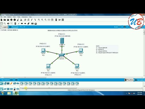
cara membangun jaringan jenis topologi star, 1 server, 1 switch, 4 pc pada cisco packet tracer

PENGERTIAN DAN PENJELASAN TOPOLOGI STAR

Merancang-Bangun Jaringan dengan Aplikasi Cisco Paket Tracert Version Mobile

Basics of Cisco Packet Tracer (Part 2) | Hub

Step-by-Step Tutorial: Setting up Bus Topology in Cisco Packet Tracer 2024 (FAST)

Konfigurasi Mudah DHCP SERVER di Cisco Packet Tracert dengan 1 Server 1 Switch 3 Client
5.0 / 5 (0 votes)
