Prinsip dasar sistem kerja rangkaian boost converter
Summary
TLDRThis video explains the basic principles and operation of a bus converter circuit. It focuses on how the circuit, typically found in LCD TVs or LED backlight power supplies, converts input voltage into a higher output voltage using components like inductors, MOSFETs, diodes, and capacitors. The working mechanism relies on PWM (Pulse Width Modulation) signals to control the switching of the MOSFET, with a demonstration showing how varying the frequency of the signal impacts the output voltage. The video also briefly touches on the use of a NE555 timer IC for generating PWM signals.
Takeaways
- 😀 The bus converter circuit is designed to increase the input voltage to a higher level.
- 😀 The bus converter is commonly used in LCD TVs, wheelchairs, and for supplying backlight voltage to LEDs.
- 😀 The circuit operates using PWM (Pulse Width Modulation) to generate a high-frequency signal.
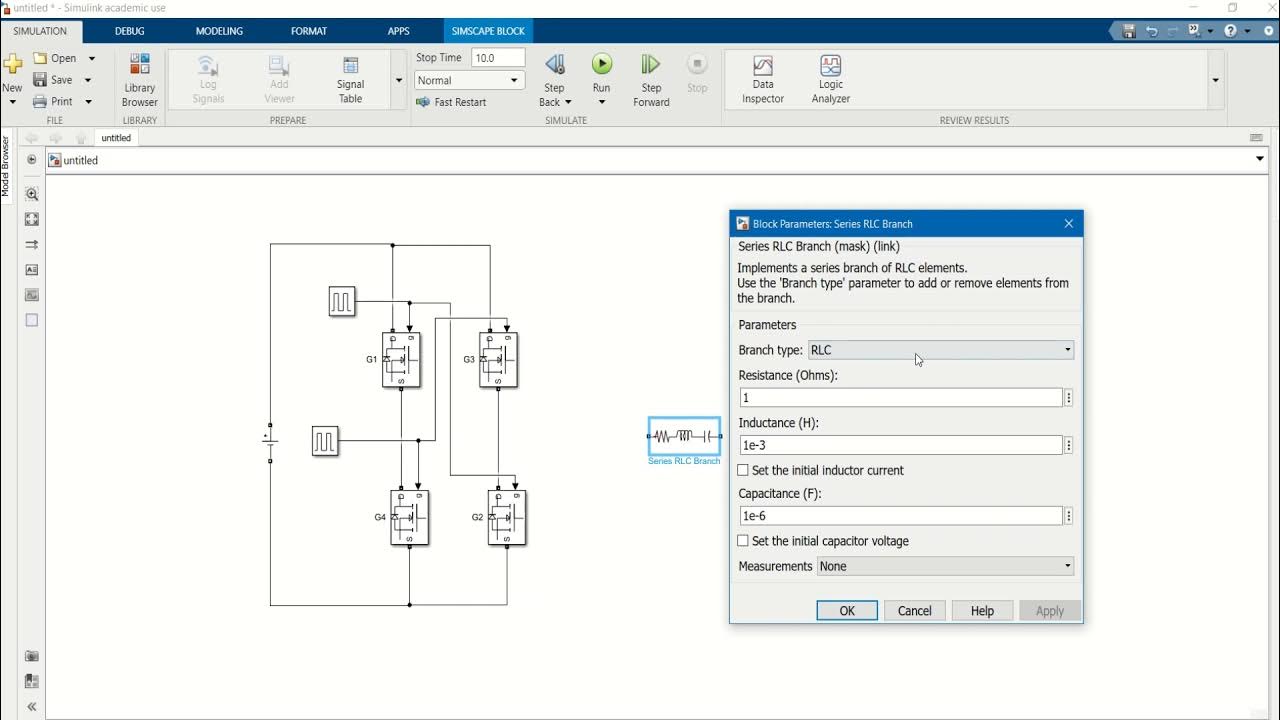
- 😀 Key components in the bus converter include an inductor, MOSFET (or transistor), diode, capacitor, and PWM signal.
- 😀 The inductor (L1) helps smooth out current flow and generates high voltage when the MOSFET is switched.
- 😀 The diode (D1) redirects current from the inductor back to the system.
- 😀 The capacitor (C1) filters the current and smooths the output from the inductor and diode.
- 😀 The MOSFET (S1) acts as a switch for the magnetization and demagnetization of the inductor.
- 😀 The MOSFET requires a PWM signal to operate properly, allowing for frequency control and higher output voltage.
- 😀 The frequency of the PWM signal influences the output voltage – faster switching results in a higher output voltage.
- 😀 A simple way to generate a PWM signal is through circuits involving inductors, resistors, capacitors, or ICs such as the NE555 timer.
Q & A
What is the purpose of a bus converter circuit?
-A bus converter circuit is used to increase the input voltage, typically found in devices like LCD TVs or LED backlights, where higher voltage is required for specific components.
What are the key components of a bus converter circuit?
-The key components include an inductor (L1), MOSFET or transistor, diode (D1), capacitor (C1), and a PWM signal generator.
How does the inductor work in the bus converter circuit?
-The inductor (L1) smooths the current flowing from the input voltage and helps generate high voltage when the MOSFET is switched on, due to the process of magnetization and demagnetization.
What role does the MOSFET play in the bus converter circuit?
-The MOSFET functions as a switch that controls the magnetization and demagnetization of the inductor. It is driven by a PWM signal to regulate the voltage.
Why is a PWM signal important for the MOSFET operation?
-The PWM signal provides the necessary frequency to switch the MOSFET on and off, controlling the power and voltage output of the circuit. The frequency and duty cycle of the PWM signal affect the output voltage.
What does the diode (D1) do in this circuit?
-The diode (D1) allows the current to flow back from the inductor (L1) to the circuit, ensuring the current direction is maintained correctly during the switching process.
What is the role of the capacitor (C1) in the bus converter circuit?
-The capacitor (C1) filters and smooths the current coming from the inductor and diode, stabilizing the voltage output.
How does increasing the switching frequency of the MOSFET affect the output voltage?
-Increasing the switching frequency of the MOSFET results in a higher output voltage. The faster the MOSFET switches on and off, the greater the voltage generated.
What was demonstrated in the first experiment in the video?
-In the first experiment, applying direct voltage to the gate of the MOSFET without a PWM signal showed that the circuit doesn't work, as the MOSFET requires both voltage and a PWM signal to operate.
How does pressing and releasing the button affect the output voltage in the second experiment?
-In the second experiment, pressing and releasing the button repeatedly simulates a PWM signal, which increases the output voltage. The faster the button is pressed and released, the higher the output voltage becomes.
What is the recommended way to generate the PWM signal for the bus converter circuit?
-The PWM signal can be generated using a simple circuit that combines components like an inductor, resistor, and capacitor, or with an integrated circuit such as the popular 555 timer IC.
Outlines

هذا القسم متوفر فقط للمشتركين. يرجى الترقية للوصول إلى هذه الميزة.
قم بالترقية الآنMindmap

هذا القسم متوفر فقط للمشتركين. يرجى الترقية للوصول إلى هذه الميزة.
قم بالترقية الآنKeywords

هذا القسم متوفر فقط للمشتركين. يرجى الترقية للوصول إلى هذه الميزة.
قم بالترقية الآنHighlights

هذا القسم متوفر فقط للمشتركين. يرجى الترقية للوصول إلى هذه الميزة.
قم بالترقية الآنTranscripts

هذا القسم متوفر فقط للمشتركين. يرجى الترقية للوصول إلى هذه الميزة.
قم بالترقية الآنتصفح المزيد من مقاطع الفيديو ذات الصلة
Design of DC AC Converter Using MATLAB SIMULINK

3 Phase Semiconverter | Power ELectronics | Lecture 61

Understanding your Consumer Unit (Fuse Board) Overcurrent & RCD Protection plus Isolation Features
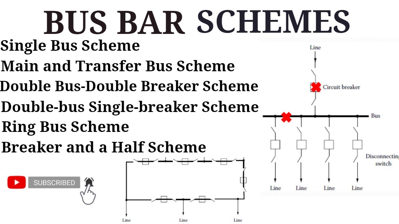
All Bus Bar Schemes in Substation | Electrical power system | With Advantages and Disadvantages

KENAPA DISEBUT PENGUNCI KONTAKTOR ?

Electro Pneumatics Prac - Exercise 1
5.0 / 5 (0 votes)
