Analog output from PWM and a low-pass filter
Summary
TLDRThe video explains how to generate analog voltages using PWM with an RC low-pass filter on the PIC32 microcontroller, which lacks a built-in DAC. It discusses the limitations of digital outputs and explores the function of RC filters in smoothing PWM signals into stable voltages. Key concepts include the relationship between frequency, resistor-capacitor values, and the resultant analog output. The tutorial also highlights the importance of selecting appropriate frequencies for effective filtering while balancing resolution and response time. Practical observations using an oscilloscope illustrate the effects of changing duty cycles and frequencies on the output voltage.
Takeaways
- 🔌 The PIC32 microcontroller primarily outputs digital signals (0 or 3.3 volts) and lacks a built-in digital-to-analog converter (DAC).
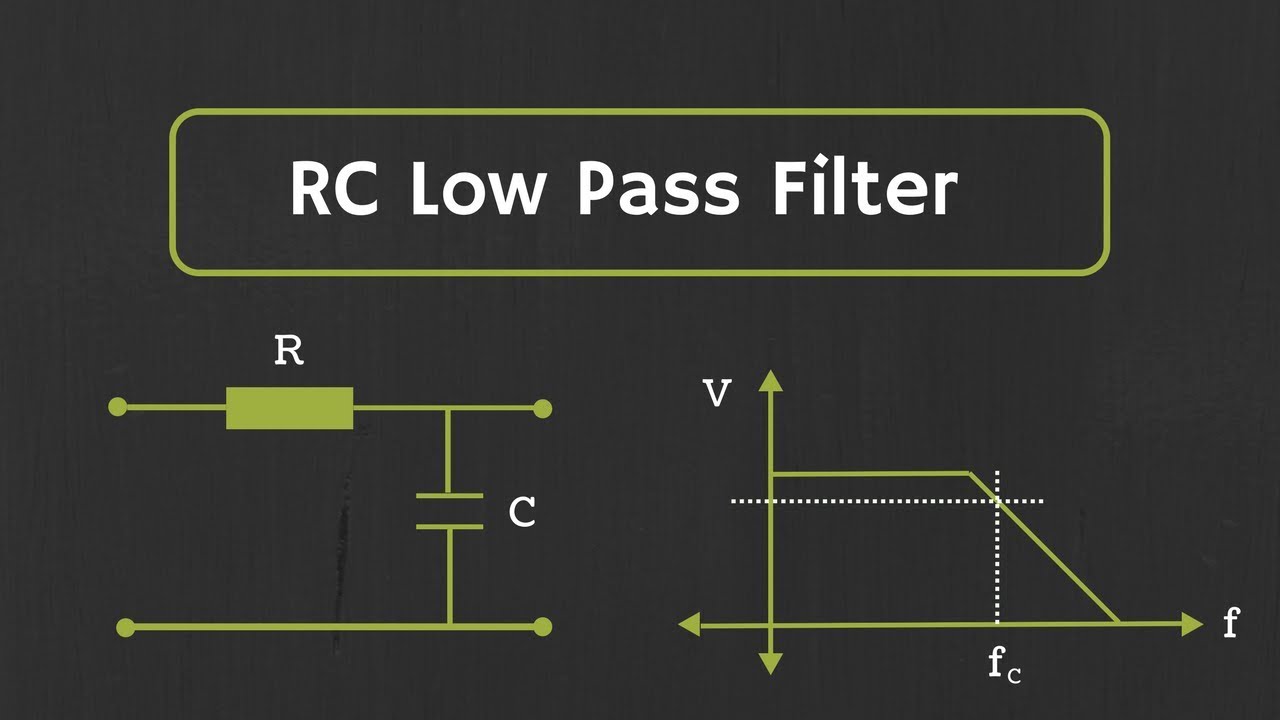
- ⚙️ To create an analog voltage, external components like a low-pass RC filter can be used to smooth PWM signals.
- 📈 The RC low-pass filter consists of a resistor and capacitor, which together define the cutoff frequency and affect the signal output's smoothness.
- 📉 If the PWM frequency is lower than the cutoff frequency, the analog output will closely resemble the input PWM signal.
- 🔄 The relationship between the resistor and capacitor values determines how quickly the output voltage can change in response to PWM adjustments.
- 🌊 As the PWM frequency increases, the output voltage becomes smoother, with less peak-to-peak variation.
- 🛠️ Choosing the right R and C values is critical for optimizing the filter's performance and ensuring a stable output.
- 📊 The cutoff frequency should be at least ten times higher than the maximum frequency of the PWM to effectively filter out high-frequency components.
- 🖥️ Using an oscilloscope allows for visual observation of the input PWM signal and the resulting analog output from the filter.
- 📏 Higher PWM frequencies can limit the number of discrete duty cycles available, impacting the resolution of the analog output.
Q & A
What is the primary limitation of the PIC32 regarding analog output?
-The PIC32 does not have a built-in Digital-to-Analog Converter (DAC) for general use, limiting it to digital output pins that can only provide either 0 volts or 3.3 volts.
How can analog voltages be generated using the PIC32?
-Analog voltages can be generated by using Pulse Width Modulation (PWM) combined with an RC low-pass filter, which smooths out the PWM signal into a continuous analog voltage.
What is the function of an RC low-pass filter in this context?
-An RC low-pass filter smooths the rapid switching of the PWM signal, allowing it to produce a stable average voltage output by charging and discharging the capacitor.
What factors influence the choice of resistor (R) and capacitor (C) values in the RC filter?
-The choice of R and C values is influenced by the desired cutoff frequency of the filter, which should ideally be at least ten times higher than the frequency of the PWM signal being used.
What is the cutoff frequency, and why is it important?
-The cutoff frequency is the point at which the output signal begins to be attenuated. It is important because it determines how effectively the filter can smooth the PWM signal without losing the desired signal characteristics.
What happens to the output voltage when the PWM frequency is increased?
-As the PWM frequency increases, the RC filter smooths out high-frequency components, resulting in a more stable and constant analog output voltage.
What challenges arise when using a low PWM frequency?
-Using a low PWM frequency can result in significant fluctuations in the output voltage, making it less stable and slower to respond to changes in the duty cycle.
How does the duty cycle affect the output voltage of the PWM signal?
-The duty cycle determines the proportion of time the PWM signal is high versus low. A higher duty cycle results in a higher average output voltage, while a lower duty cycle yields a lower average output voltage.
What is the significance of monitoring the output voltage with an oscilloscope?
-Monitoring the output voltage with an oscilloscope allows users to visualize how the output responds to changes in duty cycle and frequency, providing insights into the effectiveness of the RC filter and the stability of the analog output.
What is a practical application for generating analog voltages with the PIC32?
-A practical application could include controlling the brightness of an LED by generating varying average voltages through PWM and an RC filter, allowing the LED to be dimmed or brightened smoothly.
Outlines

هذا القسم متوفر فقط للمشتركين. يرجى الترقية للوصول إلى هذه الميزة.
قم بالترقية الآنMindmap

هذا القسم متوفر فقط للمشتركين. يرجى الترقية للوصول إلى هذه الميزة.
قم بالترقية الآنKeywords

هذا القسم متوفر فقط للمشتركين. يرجى الترقية للوصول إلى هذه الميزة.
قم بالترقية الآنHighlights

هذا القسم متوفر فقط للمشتركين. يرجى الترقية للوصول إلى هذه الميزة.
قم بالترقية الآنTranscripts

هذا القسم متوفر فقط للمشتركين. يرجى الترقية للوصول إلى هذه الميزة.
قم بالترقية الآنتصفح المزيد من مقاطع الفيديو ذات الصلة
RC Low Pass Filter Explained

First Order RC Low Pass Filter | Construction, Working, Cut Off Frequency Derivation | Simplified |

Low Pass Filters and High Pass Filters - RC and RL Circuits

Why do I need a DAC??
RC High Pass Filter Explained

How to: Gorgon City “Voodoo” Bass in Serum #samsmyers #sounddesign #shorts
5.0 / 5 (0 votes)
