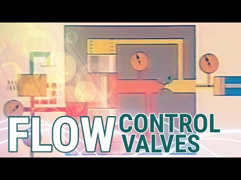
How Pneumatic Control Valve Works | Control Valve Actuator Types | Control Valve Positioner Types
Summary
TLDRThis video script delves into the world of control valves, essential in regulating industrial processes like temperature and pressure. It introduces the components of a control valve, including the body, bonnet, plug, actuator, and positioner. The video explains how a positioner translates PLC commands into actuator movements, using an example of controlling liquid temperature in a tank. It also covers different types of actuators and positioners, highlighting the benefits of digital positioners for precise control and easy calibration through digital communication protocols.
Takeaways
- 🔄 **Control Systems Overview**: The script explains the necessity of a control system, including a PLC (Programmable Logic Controller), sensors, transmitters, and a final control element like a pump or valve, to manage process parameters such as temperature and pressure.
- 🛠️ **Role of Control Valves**: Control valves are not just for starting and stopping flow but also for throttling it to achieve specific process goals like regulating temperature or liquid levels.
- 🌡️ **Temperature Control Example**: An example is given where a control valve regulates the temperature of a liquid in a tank by controlling the flow of a heat-generating additive.
- 📡 **PLC and Sensor Integration**: The PLC sends commands to the control valve based on its logic and feedback from temperature sensors, typically using a 4-20mA DC signal.
- 🔧 **Positioner and Actuator Functions**: The positioner acts as an interface between the PLC and the actuator, converting the PLC's signal into a form that the actuator can use to move the valve stem.
- 💬 **Signal Conversion Process**: The positioner contains an I to P Transducer that converts the electrical current signal from the PLC into a pneumatic signal that the actuator can understand.
- 🔌 **Electro-Pneumatic Positioners**: These positioners are used with pneumatic actuators and include an I to P Transducer to convert electrical signals to pneumatic pressure.
- 🔄 **Feedback Mechanism**: Both the PLC and the positioner require feedback to ensure the valve is adjusted correctly; the positioner receives mechanical feedback from the control valve.
- 📱 **Digital Positioners**: These use a microprocessor for more accurate control and can communicate with the PLC or DCS using digital protocols, simplifying calibration and allowing for remote feedback.
- 🔑 **Actuator Types**: Actuators are categorized into Pneumatic, Hydraulic, Electric, and Manual, with pneumatic actuators being the most common due to their simplicity and safety.
- ❓ **Engagement Invitation**: The script concludes with an invitation for viewers to ask questions or share experiences with control valves, and to subscribe for more content.
Q & A
What is the primary function of a Programmable Logic Controller (PLC) in a control system?
-A PLC is used to control various parameters of a process, such as temperature and pressure, by sending commands to final control elements like pumps, heaters, or control valves.
What are the main components required to send data to a PLC?
-Sensors and transmitters are needed to collect data and send it to the PLC for processing and control.
What is a 'Final Control Element' in the context of a control system?
-A Final Control Element is a piece of equipment, such as a pump, heater, or control valve, that carries out the commands issued by the PLC.
How do control valves differ from regular valves in terms of their function?
-Control valves are not only used to fully start and stop the flow but also to control, adjust, or throttle the flow of a liquid for precise process control, such as temperature or level control.
What is a 'Globe valve' and what are its main parts?
-A Globe valve is a common type of control valve that includes the body through which fluid passes, the bonnet that covers the inner parts, the plug that controls the flow, and the actuator that moves the plug.
What is the role of an 'Actuator' in a control valve system?
-An Actuator transfers mechanical power to the plug of a control valve using a stem, receiving commands from the Positioner to open or close the valve.
What is the purpose of a 'Positioner' in a control valve system?
-A Positioner serves as an interface between the PLC and the Actuator, adjusting the plug's position to open or close the valve precisely according to the PLC's commands.
How does a Positioner convert the PLC's command signal into a signal that the Actuator can understand?
-A Positioner contains an 'I to P Transducer' that converts the 4-20mA DC electrical current signal from the PLC into a 3-15PSI pneumatic air pressure signal for the Actuator.
What is the significance of the 'Air supply' input in a Positioner?
-The Air supply input provides clean, filtered, and regulated air with sufficient pressure to the Positioner, which, along with a built-in pressure amplifier, enables the conversion of the pneumatic signal into enough force to move the Actuator.
How does a Positioner receive feedback to ensure the valve is opened to the correct percentage?
-A Positioner receives mechanical feedback from the control valve, which allows it to adjust the valve stem position precisely to match the command from the PLC.
What are the three main categories of Positioners mentioned in the script?
-The three main categories of Positioners are Electro-Pneumatic Positioners (I/P Positioners), Pneumatic Positioners, and Digital Positioners or Digital Valve Controllers.
How do Digital Positioners differ from other types of Positioners?
-Digital Positioners use a microprocessor to replace the mechanical position feedback, allowing for more accurate valve position adjustments and the ability to communicate via digital protocols like HART or Fieldbus.
What are the four categories of Actuators mentioned in the script?
-The four categories of Actuators are Pneumatic, Hydraulic, Electric, and Manual, each with its own advantages and applications.
How can Digital Positioners improve the calibration process of control valves?
-Digital Positioners enable easier calibration of control valves using handheld communicators and digital communication protocols, reducing the need for time-consuming and difficult mechanical adjustments.
Outlines
🤖 Understanding Control Systems with PLCs and Valves
The first paragraph introduces the concept of control systems, emphasizing the need for a controller like a Programmable Logic Controller (PLC) to manage parameters such as temperature and pressure. Sensors and transmitters are highlighted as essential components that send data to the PLC, with the final control element being responsible for executing the PLC's commands, such as pumps or heaters. The paragraph also introduces the concept of control valves, which are used not only to start or stop flow but also to adjust it, with the example of a globe valve being dissected into its main parts: body, bonnet, plug, actuator, and positioner. The role of the positioner as an interface between the PLC and the actuator is explained, along with the variety of actuator and positioner types that will be explored later in the video.
🔧 The Mechanics of Positioners and Actuators in Control Valves
The second paragraph delves into the operation of positioners and actuators within control valves, using the example of controlling the temperature of a liquid in a tank by regulating the flow of an additive. The PLC's decision-making process based on its logic and feedback from a temperature sensor is explained, along with how the positioner acts as a translator between the PLC's signal and the actuator's language. The conversion of the 4-20mA electrical current signal to a pneumatic signal is detailed, including the role of the I to P Transducer. The importance of the air supply and the positioner's feedback mechanism for precise valve positioning is also discussed. The paragraph concludes with an overview of the different types of positioners, including Electro-Pneumatic, Pneumatic, and Digital, each with their unique features and applications. Additionally, a brief introduction to the classification of actuators into Pneumatic, Hydraulic, Electric, and Manual is provided, setting the stage for further exploration in the video.
Mindmap
Keywords
💡Control
💡Programmable Logic Controller (PLC)
💡Sensors and Transmitters
💡Final Control Element
💡Control Valve
💡Globe Valve
💡Actuator
💡Positioner
💡I to P Transducer
💡Pneumatic Signal
💡Digital Positioner
💡Actuator Types
Highlights
Importance of control over parameters like temperature and pressure in processes.
Use of Programmable Logic Controllers (PLC) for process control.
Role of sensors and transmitters in sending data to PLC.
Definition and function of a 'Final Control Element' in a control system.
Introduction to control valves and their purpose in throttling the flow of liquids.
Explanation of how control valves can regulate temperature or liquid levels.
Description of a 'Globe valve' and its components.
Function of the 'Actuator' in transferring mechanical power to control the valve.
Role of the 'Positioner' as an interface between PLC and Actuator.
Types of Actuators and Positioners in control systems.
Example of controlling liquid temperature in a tank using a control valve.
How PLC commands are sent and interpreted by the control valve system.
Conversion of PLC signals to pneumatic signals by an electro-pneumatic positioner.
Explanation of the 'I to P Transducer' and its function in signal conversion.
Importance of air supply and pressure amplification in actuator movement.
Mechanical feedback mechanism from the control valve to the Positioner.
Categories of Positioners: Electro-Pneumatic, Pneumatic, and Digital.
Advantages of Digital Positioners and their use of microprocessors.
Communication protocols like HART or Fieldbus for valve control and feedback.
Standalone I/P transducers for less critical accuracy applications.
Classification of Actuators into Pneumatic, Hydraulic, Electric, and Manual types.
Discussion on the use and advantages of Spring-and-Diaphragm actuators.
Invitation for viewer questions and comments on control valve experiences.
Transcripts
We would almost always like to have control over different parameters of the process
like temperature, pressure, level, and so on
To achieve this, obviously, we need a controller
like Programmable Logic Controller or PLC for short
We also need some sensors and transmitters to send data over to PLC
Finally, we need a piece of equipment to carry out the PLC’s commands
which usually called as “Final Control Element”
A Final Control element can be a pump, a heater, a control valve, and so on
If you would like to figure out how control valves exactly work
via an interesting practical example, stay with us to the end of this video
If you like this style of video, subscribe
and click the bell to receive notifications of new videos by Upmation
Very often by “Control Valves” we mean the type of valves
that are used not only to fully start and fully stop the flow
but also to control or adjust or in other words throttle the flow of the liquid
By throttling the flow, we achieve our final purpose that is
for example, controlling the temperature of a furnace
or the level of a liquid inside a tank
You may say how it is possible!
Don’t worry! We are going to talk about it in detail.
Well, this is a “Globe valve”; One of the most common types of control valves
Let’s take a quick look at its different parts
This is the “Body” of the valve that the fluid will pass through it
and this is the Bonnet that is connected to the body and covers its inner parts
We call this part Plug
The plug will control, Stop or Start the flow
by exposing the liquid flowing inside the pipe.
This part here is the “Actuator” that transfers
the mechanical power to the plug using the “Stem”
The Actuator will receive the commands from the Positioner
The main role of the “Positioner” is to be an interface between the PLC
and the Actuator to precisely adjust the plug for being open or closed
There are a variety of Actuator and Positioner types
and we are going to check them all at the end of this video
So, let’s start with an example to understand the operation
of the Positioner and its relation to the PLC and Actuator
In this example, we aim to control the temperature of a liquid within a tank
by regulating the flow of an additive
This additive will generate heat by having a
chemical reaction with the liquid already inside the tank.
Say the PLC decides to send a 50% open command to the control valve
This command is based on two items
First, the PLC logic
and second, the feedback it has received by the temperature sensor
installed on the tank
This command signal often is in the form of a 4-20mA DC electrical current
and is sent from the PLC
The device that receives this signal on the field
is the “Positioner” of the control valve
As we are using a specific type of pneumatic actuator in this example
which needs compressed air to become activated
therefore we chose an electro-pneumatic positioner
Don’t worry about the names at the moment!
In this case, the positioner plays the role of a “translator”
and converts the PLC language to the actuator language!
It means that the Positioner will convert the 4-20mA signal
to an air pressure signal
How it happens?
Well, inside of this Positioner we have a
converter unit which is called “I to P Transducer”
In fact, this transducer converts the 4mA DC current
to a 3PSI air pressure
and the 20mA DC current to a 15PSI air pressure
and of course, they are proportional in the middle range
We call 3-15PSI air pressure as the “Pneumatic Signal”
So with a simple calculation, we understand that
in order for the PLC to open the valve for 50% of its full range
it should send a 12mA signal to the Positioner
Then the Positioner will convert it to a 9PSI signal accordingly
and will send it directly to the actuator
But wait!
It sounds like the 9PSI pressure is not enough to move the actuator
Therefore, we need another input to the Positioner as the “Air supply”
The Air supply input will provide us with a clean, filtered, regulated air
with sufficient pressure, thanks to this filter/regulator device
After all, using the Air supply input and a built-in pressure amplifier
the positioner will be able to convert the 9PSI pressure signal
to sufficient air pressure for moving the actuator to the right amount
Now, we see that the actuator is able to overcome its spring force
and so far so good!
But same as the PLC that requires feedback by the sensor
to decide about the command it is going to send
the Positioner also needs to receive feedback
to precisely position the valve stem and open the valve to 50%.
This feedback is sent by the “control valve” to the Positioner
using a mechanical mechanism
In this way, the Positioner will decide how much pressure
the actuator needs to move the valve stem
In general, Positioners come into three different categories;
First, the “Electro-Pneumatic” Positioners or I/P Positioners
that we already discussed in the example
Second, the “Pneumatic” Positioners, in which their control signal
is a pneumatic signal and they do not need any I/P Transducer modules integrated
The last is “Digital” Positioner or “Digital Valve Controller”
In addition to an “I to P Transducer”
these positioners take advantage of a “Microprocessor”
to fill in the place of the mechanical position feedback.
The input signal or setpoint from the PLC will directly send to the Microprocessor
The valve position feedback which is measured electronically
will also enter the Microprocessor
Comparing these two electronic signals
the Microprocessor is able to adjust the valve position
quite accurately in comparison with the other types of positioners.
Using Digital Positioners, we are able to communicate with the valve
by different types of protocols such as HART or Fieldbus protocols like Profibus
By such digital communications, we can calibrate control valves
way more easily using and-held communicators
without tackling time-consuming and sometimes difficult mechanical adjustments
Besides, we can send some feedbacks from the control valve to the PLC
or DCS via these communication protocols
The last point is that the standalone I/P transducers can control the valve
independently in case that the accuracy is of less importance
Meaning that, they are not integrated into any kind of positioners
and therefore there is no feedback in this case
Now that we’ve got introduced to the positioners
let’s get into the Actuators and their different types
Generally, we can classify the Actuators into four different categories
Pneumatic, Hydraulic, Electric, and Manual
The Pneumatic actuators are the most used kinds of actuators
due to their simple design
fairly low price and of course being Intrinsically Safe
Electric Actuators have an electric motor inside
In the first place, they had been designed for on/off applications
but nowadays some of them are upgraded for continuous control applications
The primary application of them
is in the locations that we don’t access the compressed air
In this video, we learned how a Spring-and-Diaphragm actuator
along with an Electro-Pneumatic Positioner
adjusts the valve in order for the valve
to control the flow of the liquid according to the PLC commands
Well, it’s time to ask us your question
or tell us about your experiences dealing with the control valves in the comments
Again if you like these kinds of videos please subscribe
and tell us which subjects you are most interested in
Thanks for watching!
تصفح المزيد من مقاطع الفيديو ذات الصلة
5.0 / 5 (0 votes)