EPANET Tutorial 02.03 - Project Setup | Hydraulic Modeling
Summary
TLDRIn this tutorial, Mark Wilson, founder of A Q Model, guides viewers through setting up a project in EPANET version 2.3, focusing on project defaults and ID labels. He explains how to use auto-increment for unique identifiers, set property defaults for nodes and pipes, and choose flow units between SI and English standards. Wilson also touches on head loss formulas, accuracy settings, and default patterns, providing foundational knowledge for hydraulic modeling enthusiasts.
Takeaways
- 📚 The video is a tutorial by Mark Wilson, founder of a Q model, focusing on EPANET version 2.
- 🔍 It follows the EPANET User's Manual, section by section, with advanced topics in a separate playlist.
- 🏗️ The tutorial covers project setup, specifically section 2.3 of the manual.
- 🆔 Discusses 'Project Defaults' and the importance of setting ID labels for auto-generated IDs.
- 📏 Explains how to set property defaults like node elevation, tank diameter, height, and pipe length.
- 🔗 Highlights the use of 'auto lengths' for calculating pipe length based on a properly set background map.
- 🌀 Details the significance of choosing the right flow units, which affects all units in the model including length and diameter.
- 🔢 Points out that the core unit in EPANET is cubic feet per second (CFS) and feet, with other settings converted in the background.
- ⚙️ Mentions the selection of head loss formula (Hazen-Williams, Darcy-Weisbach, or Manning) and the importance of accuracy settings.
- 🚫 Advises against setting the accuracy too high to avoid node continuity problems.
- 🌧️ Notes the default pattern setting in EPANET, which can affect how unassigned demands are handled.
- 🖼️ Discusses view dimensions and options for setting up the map area and model visualization.
Q & A
Who is the speaker in the video?
-The speaker is Mark Wilson, the founder of a Q model.
What is the main topic of the video?
-The main topic is the project setup in EPANET version two, as outlined in section 2.3 of the EPANET user's manual.
What is the purpose of the 'ID labels' tab in the project defaults?
-The 'ID labels' tab is used to prepend a piece of text to each automatically generated ID, helping to identify and organize model components.
Why is it important to set the flow units at the beginning of the project?
-Setting the flow units at the beginning is crucial as it determines whether the model uses SI units or English standard units, affecting all related measurements such as length and diameter.
What is the significance of the 'auto increment' in the ID labels tab?
-The 'auto increment' ensures that each new ID is unique, incrementing by a set number after each entry, which is essential for distinguishing different model components.
What is the default flow unit in EPANET, and why is it important?
-The default flow unit in EPANET is cubic feet per second (CFS). It's important because it serves as the core unit for all flow-related calculations in the model.
What are the three options for head loss formula in EPANET?
-The three options for head loss formula are Hazen-Williams, Darcy-Weisbach, and Jessen-Manning.
Why might a user choose a non-standard value for pipe roughness, such as 19.99?
-A non-standard value like 19.99 can serve as a flag to indicate that no engineering judgment was used in determining the roughness, allowing for adjustments during the calibration process.
What is the role of the 'default pattern' setting in EPANET?
-The 'default pattern' setting ensures that any demand not specifying a pattern other than one will adopt that pattern, which can be crucial for uniformity in demand distribution.
What does the 'global demand multiplier' setting do in the model?
-The 'global demand multiplier' allows for quick adjustments to peak demands, such as during the max day or max hour, providing a simple way to scale demand across the model.
Why is the 'view options' section important for the model setup?
-The 'view options' section is important for setting up the visual aspects of the model, including symbology, flow arrows, and background color, which aid in the model's interpretation and analysis.
Outlines
🛠️ EPA Net Project Setup Basics
Mark Wilson introduces the tutorial series on EPA Net version two, focusing on project setup as outlined in section 2.3 of the EPA Net user's manual. He explains the importance of setting project defaults, including ID labels which are prepended to automatically generated IDs, and the selection of an auto-increment for the latter part of the ID. He also discusses other property defaults such as node elevation, tank diameter, height, pipe length, and the option to use auto lengths based on map defaults. The tutorial touches on the significance of flow units in determining whether the model uses SI or English standard units, and the core unit of CFS in EPA Net. Mark also mentions the head loss formula options and the importance of setting the accuracy for model simulations to avoid node continuity problems.
📏 Advanced EPA Net Settings and View Options
In the second part of the video script, Mark delves into more advanced settings of the EPA Net model, including the stop setting for model imbalances, default pattern considerations, and global demand multipliers for adjusting peak demands. He also addresses less commonly modified settings such as emitter status report, check frequency, and max check damp limit, promising to cover these in future advanced videos. The tutorial concludes with a discussion on view options, where viewers are informed about setting up the map area, map units, and the appearance of the model, including symbology, flow arrows, and background color. Mark encourages viewers to stay tuned for the rest of the video series to learn more.
Mindmap
Keywords
💡EPA net
💡Hydraulic modeling
💡Project setup
💡ID labels
💡Auto increment
💡Flow units
💡Head loss formula
💡Calibration
💡Node continuity
💡Pattern ID
💡View options
Highlights
Introduction to the EPA net version two tutorial series by Mark Wilson, the founder of a Q model.
Discussion of project setup as outlined in section 2.3 of the EPA net user's manual.
Explanation of project defaults and the use of ID labels for automatically generated IDs.
The importance of selecting an auto increment for the latter part of the ID in project setup.
QuickStart tutorial reference and its indication of not using certain ID settings.
Property defaults for nodes, tanks, diameters, heights, and pipe lengths in hydraulic modeling.
Use of auto lengths for calculating pipe lengths based on map defaults.
The option to use auto link for generating pipe length or manually adjusting for schematic models.
Setting default pipe diameter and roughness with a flag value for later calibration.
The significance of flow units in determining the model's use of SI or English standard units.
Core unit in EPA net is CFS, and other settings are converted using a conversion factor.
Head loss formula options: Hazen Williams, Darcy Weisbach, and Manning's formula.
The common use of Hazen Williams in the water industry for hydraulic modeling.
Accuracy settings and the potential for node continuity problems with higher values.
The use of stop settings to halt simulations when the model becomes unbalanced.
Default pattern settings in EPA net and their impact on unassigned demand patterns.
Global demand multiplier as a tool for adjusting peak demands during model calibration.
Advanced topics such as emitter status report, check frequency, and max check damp limit to be covered in future videos.
Setting up view dimensions and map area for hydraulic modeling, including auto size feature.
View options for model symbology, flow arrows, and background color customization.
Closing remarks and invitation to subscribe for more tutorials in the series.
Transcripts
hello folks my name is Mark Wilson and
I'm the founder of a Q model where we
inspire confidence in hydraulic modeling
this is another video in tutorial series
on EPA net version two in this video
we'll be calling a following along with
the EPA net user's manual as far as
section by section and then it will also
post more advanced videos in another
playlist today we're going to talk about
project setup that's section 2.3 of the
user's manual the first item of setup I
want to show you is the project defaults
so when we open up the project defaults
the first tab is the ID labels now what
happens here is any piece of text that
you type in here will be prepended to
each automatically generated ID so
typically you'll do something like J -
or J underscore and then you also need
to select an auto increment for the
latter part of the ID so in this
scenario our first ID would be J - 1 and
then once we create another one it would
be J - 2 etc etc the QuickStart tutorial
in the users guide indicates that none
of those will be used so we'll just
leave that blank other property defaults
you can give it a node elevation tank
diameter height pipe length you can
switch to auto lengths so this will
based on the map defaults that we'll set
here in just a minute we'll give
automatically calculate the length this
is used mostly if you've got a
background map and you're tracing over
the background and you've set it up
properly you can use auto link to
generate the pipe length otherwise you
probably want to leave that off and get
a default
then just change it manually if you're
doing more of a schematic model you've
got a default pipe diameter and
roughness a lot of times what I'll do is
choose a more realistic one but put a
flag value off to the end like one 19.99
the 0.99 is kind of a flag value you can
do anything like one point five point
five five it's really the decimal part
that kind of gives you a excuse me that
gives you an indication that no
engineering judgment was used in
determining that roughness but then when
you get into calibration you can you can
round those off and use a more
thought-out value as far as hydraulics
goes you've got flow units this is very
important one to set up in the beginning
this determines whether the model uses
SI units or English standard units so
any flow unit that you choose here that
is English will mean that everything
else is in English units such as your
length diameter etc one thing to note
that the core unit in EPA net is CFS
cubic feet per second and feet
everything else is that you if you
choose other settings it's just
converted in the in the background with
a conversion factor and it's also good
to note that the flow unit this is kind
of a unwritten when we're talking flow
units this not only goes for flow in the
pipe but also the demand the UN ran for
each Junction will be in these Samians
so pipe flow as well as junction demand
you can choose from three options for
head loss formula Hazen Williams Darcy
Weisbach Jessie Manning typically in the
water industry we're using Hayes and
Williams and specific gravity relative
viscosity
things usually left at the default
accuracy this is one that I'll cover in
a more advanced topic this is a good
starting space though point zero zero
one you would typically try not to go
over 0.01 if you can help it
what happens if you get it too high
you're going to get some node continuity
problems so we're going to go and back
off to point zero zero one usually that
only you're only gonna have to change
that if you have a very complex network
with lots of pumps and P RVs that are
changing all over the place typically I
use this stop setting so if the model
becomes unbalanced we want to go ahead
and stop the simulation instead of
continuing and this one's a little
tricky ones default pattern this is
something inherent to EPA net and it
carries over into some other commercial
packages like info water where if you
have a pattern with an ID of one in the
model anything any demand that does not
specify a pattern other than one will
take on that one pattern and sometimes
that's a little tricky to troubleshoot
and certain models global demand
multiplier that's a quick and easy way
to peak up demands the max day or max
month back the peak hour that kind of
thing the other settings here emitter
status report check frequency max check
damp limit I'll cover those in a future
advanced video now for view we want to
look at dimensions so this one allows
you to set up what the map area will be
if you don't know what the map area is
and you're just doing it more of a
schematic model then this is fine just
to pick one and I guess the map units
don't really matter in that case because
you can override all of the length
values in the model
if you are going to use a backdrop and
trace over the top you'll want to be a
little bit more careful in setting this
up and give actual coordinates
whether that be in feet meters or
lat/long he would set these up more
correctly so that when you bring in that
background image everything is the way
you want it to be you can also do an
auto size and it will help you out with
that last thing is for view options this
is where we would set up how things look
in our model symbology flow arrows
background color etc well that's all for
now and thanks for watching stay tuned
subscribe to the rest of the video
series to learn some more
you
浏览更多相关视频
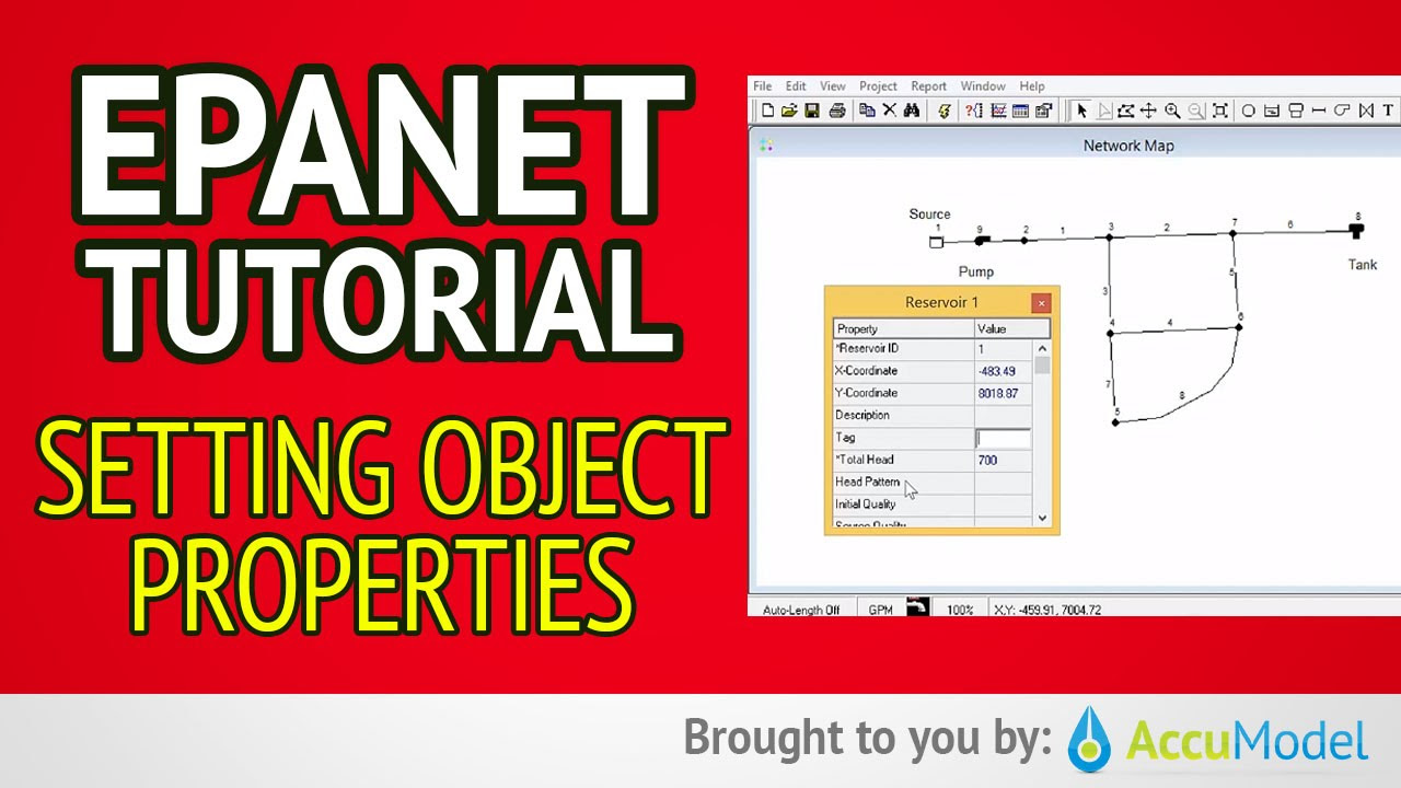
EPANET Tutorial 02.05 - Setting Object Properties | Hydraulic Modeling
EPANET Tutorial 02.07 - Running a Single Period Analysis | Hydraulic Modeling
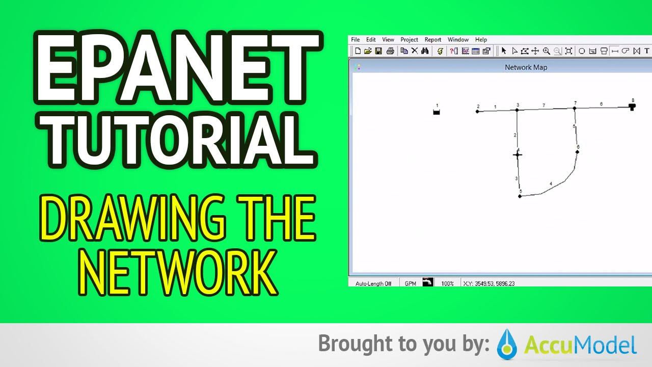
EPANET Tutorial 02.04 - Drawing The Network | Hydraulic Modeling
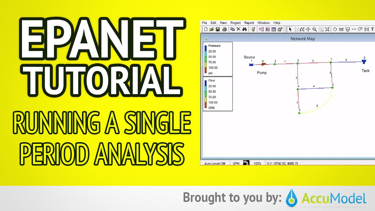
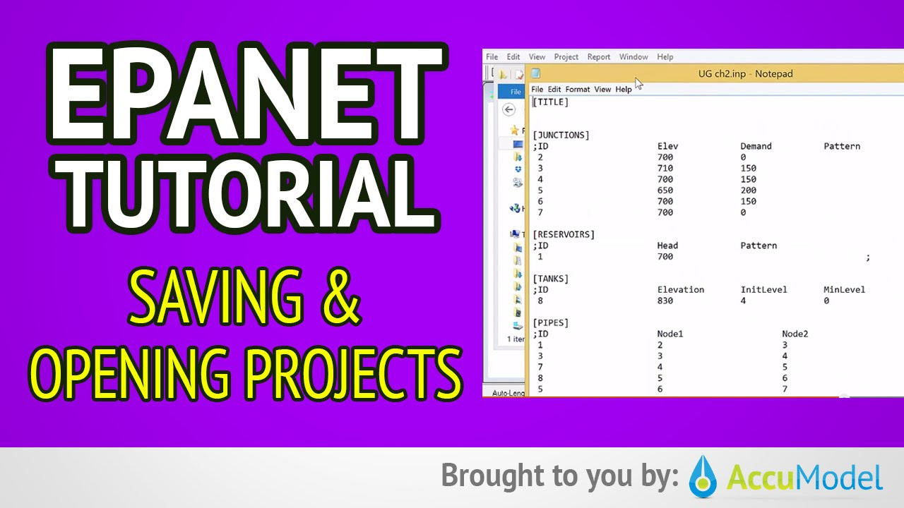
EPANET Tutorial 02.06 - Saving and Opening Projects | Hydraulic Modeling
EPANET Tutorial 01 - Overview of EPANET | Hydraulic Modeling
How to Setup the XR Interaction Toolkit - 2023 Unity VR Basics
5.0 / 5 (0 votes)