Control a Kinetix 5100 Over Ethernet with a Micro850 Controller
Summary
TLDRThis video tutorial outlines the setup process for Rockwell's Micro 800 controllers to manage Point.io Power Flex 525 drives and Kinetics 5100 drives over Ethernet. It covers identifying compatible hardware, configuring firmware and software, and programming PLC and drives. The guide also demonstrates the use of user-defined function blocks and the configuration of the Kinetics 5100 drive with the KX 5100 software, resulting in a scalable and efficient automation system.
Takeaways
- 🚀 Rockwell's updated functionality allows for cost-effective system creation with new opportunities.
- 🔍 Micro 800 controllers with 'e' after the series identifier have Ethernet control capabilities.
- 🔧 For SIP control, Micro 800 can interface with 1734-AENT IOE, PowerFlex 523/525, or Kinetics 5100 drives.
- 📦 Ensure firmware version 21 or newer and software version 21 or newer for compatibility with CCW.
- 🛠️ Download the latest User Defined Function Blocks (UFBs) for Rockwell's Kinetics 5100 from the PDCD for proper setup.
- 🔄 Import the downloaded CCW archive project into ControlLogix Configuration (CCW) for project setup.
- 📱 Configure the PLC with an IP address and set up Ethernet settings for communication with other devices.
- 🔌 Use the KX 5100 software to configure the Kinetics 5100 drive with an IP address and set it to IO mode.
- 🔑 Select the correct motor and catalog number in the drive configuration for accurate motor control.
- 🔄 Download and save the project to maintain settings and ensure offline functionality.
- 🎛️ Demonstrated control of the Kinetics 5100 drive using the Micro 850 PLC with commands like home, jog, and move.
Q & A
What is the main topic of the video script?
-The video script discusses setting up a system on a budget using Rockwell's updated functionality for controlling devices over Ethernet with Micro 800 controllers, Point.io Power Flex 525 drives, and Kinetics 5100 drives.
What does the 'e' after the series identifier in Rockwell's micro 800 product part numbers indicate?
-The 'e' after the series identifier in Rockwell's micro 800 product part numbers indicates the capability of controlling devices over Ethernet.
What are the minimum requirements for the micro 850 firmware and software versions to work with the new Ethernet functionality?
-The micro 850 firmware must be version 21 or newer, and the software must be version 21 or newer to work with the new Ethernet functionality.
Which Rockwell software is used to configure the Kinetics 5100 drive?
-The Kx5100c software is used to configure the Kinetics 5100 drive.
How can one obtain the latest user-defined function blocks (UDFBs) for the Kinetics 5100 drive?
-To obtain the latest UDFBs for the Kinetics 5100 drive, one should navigate to Rockwell's Product Compatibility and Download Center (PCDC), search for 'Kinetics 5100', select 'UD FB', and download the latest revision.
What is the purpose of assigning an IP address to the PLC, HMI, and Kinetics 5100 drive during setup?
-Assigning IP addresses to the PLC, HMI, and Kinetics 5100 drive is necessary for establishing communication between these devices over Ethernet, enabling remote control and data exchange.
What is the role of the 'Device Block' UDFB in interfacing with the Kinetics 5100 drive?
-The 'Device Block' UDFB is primarily used for interfacing with the Kinetics 5100 drive, allowing the PLC to control the drive's functions such as on, home, jog, incremental move, absolute move, and fault reset.
How does the video script describe the process of setting the IP address for the Kinetics 5100 drive?
-The video script describes setting the IP address for the Kinetics 5100 drive through the Kx5100c software after connecting to the drive via the mini USB port and confirming the IP address settings in the software.
What is the significance of configuring the Kinetics 5100 drive in IO mode?
-Configuring the Kinetics 5100 drive in IO mode allows the PLC to take control of the drive remotely and issue commands, which is essential for the system's functionality.
What steps are necessary to ensure the system is functional after configuring the PLC, HMI, and Kinetics 5100 drive?
-After configuring the PLC, HMI, and Kinetics 5100 drive, one must download the code to each device, set the motor position using the witness mark and photo eye, and test the servo on, home, jog, and move functions to ensure the system is operational.
Outlines

此内容仅限付费用户访问。 请升级后访问。
立即升级Mindmap

此内容仅限付费用户访问。 请升级后访问。
立即升级Keywords

此内容仅限付费用户访问。 请升级后访问。
立即升级Highlights

此内容仅限付费用户访问。 请升级后访问。
立即升级Transcripts

此内容仅限付费用户访问。 请升级后访问。
立即升级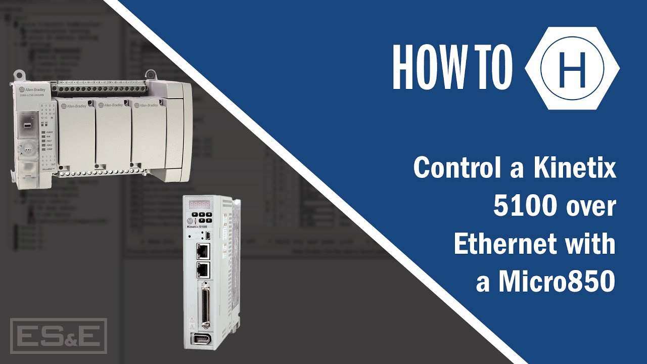


5.0 / 5 (0 votes)
