SPWM (Sinusoidal PWM) Three Phase Inverters
Summary
TLDRThis video explores three-phase voltage source inverters and sinusoidal Pulse Width Modulation (PWM) techniques. It delves into the workings of three-phase inverters, highlighting the use of triangular carrier waves to control switching transistors. The script explains the calculation of line-to-line voltages, voltage limitations based on DC link voltages, and the impact of modulation frequency on harmonic distortion. Over-modulation techniques to increase output voltage are also discussed, alongside practical considerations such as switching losses, dead times, and THD. The video aims to provide a detailed understanding of how sinusoidal PWM can be applied in three-phase inverters for efficient motor control.
Takeaways
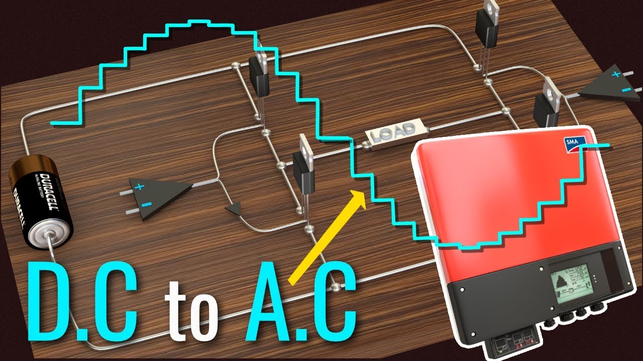
- 😀 Sinusoidal PWM in three-phase voltage source inverters operates similarly to single-phase inverters, with three-phase outputs generated from sinusoidal reference voltages.
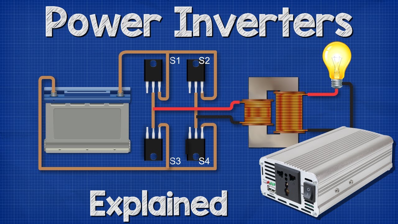
- 😀 A triangular carrier wave is compared with the reference signals, determining when the top or bottom transistors of the inverter are switched on.
- 😀 Unipolar and bipolar PWM techniques can be used for generating the necessary switching signals in three-phase systems.
- 😀 Line-to-line voltages can be derived by subtracting the phase voltages from each other.
- 😀 The voltage waveform generated by the inverter can be controlled to produce both positive and negative voltage values, limited by the DC link voltage.
- 😀 Increasing the switching frequency improves the waveform's sinusoidal nature but results in higher switching losses and may introduce dead time issues.
- 😀 Harmonics in the output voltage are influenced by the modulation frequency (MF), with higher MF resulting in a reduction of harmonics.
- 😀 Using a synchronous PWM with odd multiples of the modulation frequency helps eliminate third-order harmonics.
- 😀 In the linear region, the maximum voltage applied to the load is half of the DC link voltage, with the line-to-line RMS voltage calculated using specific formulas.
- 😀 Over modulation can be used to increase the voltage levels, but this results in additional harmonic content and a saturation of the voltage at 78% of the DC link voltage.
- 😀 RL loads, such as motors, naturally filter out high-frequency harmonics, but additional filters (e.g., LC filters) can be used to further reduce the Total Harmonic Distortion (THD).
Q & A
What is the primary topic of the video script?
-The primary topic of the video is about three-phase voltage source inverters, focusing on sinusoidal pulse width modulation (PWM) and the comparison with six-step PWM from previous discussions.
What is the key difference between unipolar and bipolar PWM techniques?
-Unipolar PWM uses a single polarity for switching, while bipolar PWM involves alternating the polarity. Both techniques compare a triangular carrier wave with a sinusoidal reference signal, but they differ in how the switching signals are generated.
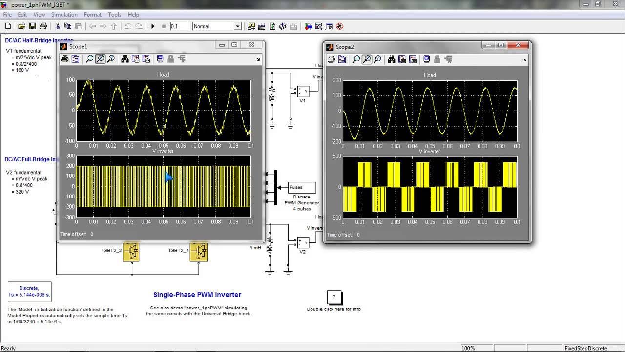
How is the voltage waveform created in a three-phase inverter using sinusoidal PWM?
-The voltage waveform in a three-phase inverter is created by comparing a triangular carrier wave with three reference sinusoidal signals for the three phases. Depending on the comparison, the inverter switches between top and bottom transistors, creating a modulated output.
What is the significance of the modulation frequency (mf) in determining harmonics?
-The modulation frequency (mf) controls the harmonic structure of the output voltage. The harmonics appear at multiples of mf, and adjusting mf helps in managing the harmonic content. A higher modulation frequency can reduce harmonics, but practical limitations like transistor switching times can restrict its value.
What happens when the modulation frequency is small or the switching frequency is increased?
-If the modulation frequency is small, it might result in larger harmonics. Additionally, increasing the switching frequency reduces harmonic distortion but leads to higher switching losses and potential issues with practical switching times in the inverter.
How do RL loads help in filtering out voltage harmonics?
-RL loads, typically used in electrical machines, have the ability to filter out higher-frequency harmonics. The impedance of the load increases with frequency, reducing the current harmonics that can be generated from the voltage harmonics.
What is the maximum line-to-line RMS voltage achievable with sinusoidal PWM in the linear region?
-In the linear region, the maximum achievable line-to-line RMS voltage is approximately 0.612 times the DC link voltage. For example, with a 540V DC link, the maximum RMS voltage would be around 330V.
What happens when the inverter enters the over modulation range?
-In the over modulation range, the inverter can produce higher voltage levels, but it introduces more harmonics. The maximum achievable voltage is around 0.78 times the DC link voltage. However, this comes with the trade-off of increased harmonic distortion.
How does the over modulation range affect the harmonic content of the waveform?
-Over modulation results in additional harmonics, including third, fifth, and seventh-order harmonics, depending on the modulation technique used. Although some harmonics, like the third-order, can be eliminated through specific modulation strategies, overall harmonic content increases.
What is the relationship between the DC link voltage and the output line-to-line RMS voltage?
-The output line-to-line RMS voltage is related to the DC link voltage through a scaling factor. In the linear region, the maximum RMS voltage is 0.612 times the DC link voltage. In the over modulation range, this value increases but saturates around 0.78 times the DC link voltage.
Outlines

此内容仅限付费用户访问。 请升级后访问。
立即升级Mindmap

此内容仅限付费用户访问。 请升级后访问。
立即升级Keywords

此内容仅限付费用户访问。 请升级后访问。
立即升级Highlights

此内容仅限付费用户访问。 请升级后访问。
立即升级Transcripts

此内容仅限付费用户访问。 请升级后访问。
立即升级浏览更多相关视频
Inverter_simulink

Penjelasan tentang Modulasi PWM dan Modulasi FM Menggunakan Proteus
Inverters, How do they work?

Inversor de Frequências _ Aula 1_ Conceitos Básicos
Power Inverters Explained - How do they work working principle IGBT

What is Pulse Width Modulation? How to generate PWM signal ? Pulse Width Modulation Explained
5.0 / 5 (0 votes)
