Fusion 360 beginner's Exercise #7 - Fusion 360 tutorial
Summary
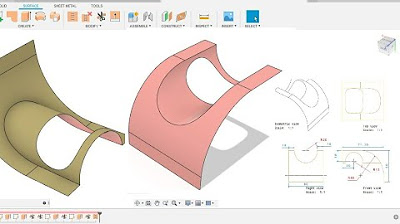
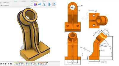
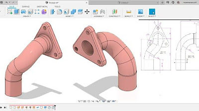
TLDRIn this tutorial video, the host demonstrates how to design a nozzle in Fusion 360 based on a subscriber's request. Using provided photos, the tutorial covers creating a circular base profile that lofts into a rectangular top profile with a constant 3mm thickness. The process includes sketching, extruding, lofting, and shelling techniques to achieve the desired nozzle shape, with additional steps for cutouts, fillets, and a slot. The video is aimed at viewers interested in CAD modeling and Fusion 360 software.
Takeaways
- 😀 The video is a tutorial on creating a nozzle design in Fusion 360 based on a subscriber's request.
- 🔍 The nozzle has a circular profile at the bottom that lofts to a rectangular profile at the top with a constant 3mm thickness.
- 📏 The design includes specific dimensions such as an inner thickness of 8mm, outer thickness of 14mm, and a total height of 65mm.
- 📐 The tutorial begins by creating a circle with an outer diameter of 49.7mm and extruding it to a height of 25mm.
- 🛠️ The upper profile of the nozzle is created by offsetting a plane 40mm above the base and sketching a 63mm wide slot.
- 🔄 Symmetry is used to ensure the design is balanced and centered around the construction lines.
- 🏗️ The tutorial involves lofting between the bottom circular profile and the top rectangular profile to form the nozzle shape.
- 🔩 The design includes a cutout for a screw hole and the use of the 'shell' command to give the component a constant thickness.
- 🛑 The tutorial assumes dimensions not provided by the user, such as the distance from the base to the top of the nozzle, and makes adjustments accordingly.
- 🔲 The final steps of the tutorial involve adding fillets and chamfers to the nozzle for a smoother finish.
- 📝 The video concludes with the creation of a triangular profile and a slot, emphasizing the importance of following the provided dimensions for accuracy.
Q & A
What is the main topic of the video tutorial?
-The main topic of the video tutorial is to demonstrate how to create a specific nozzle design in Fusion 360 based on a subscriber's request and provided photos.
What is the constant thickness of the nozzle that the tutorial covers?
-The constant thickness of the nozzle discussed in the tutorial is 3mm.
What is the outer diameter of the circle that needs to be drawn in the initial step of the tutorial?
-The outer diameter of the circle to be drawn in the initial step is 49.7mm.
How far does the tutorial instruct to extrude the initial circle?
-The tutorial instructs to extrude the initial circle to a distance of 25mm.
What is the purpose of creating the upper profile in the tutorial?
-The purpose of creating the upper profile is to form the top part of the nozzle, which is a rectangular profile that lofts from the circular profile at the bottom.
What is the total height from the bottom of the nozzle to the top point as described in the tutorial?
-The total height from the bottom to the top point of the nozzle is 65mm, which is the sum of 40mm and 25mm as described.
How does the tutorial handle the creation of the top profile's sketch?
-The tutorial creates the top profile's sketch by first creating a plane 40mm above the existing profile, then drawing the required shapes and dimensions, and using construction lines and symmetry to complete the sketch.
What command is used in the tutorial to combine the bottom and top profiles of the nozzle?
-The tutorial uses the 'Loft' command to combine the bottom and top profiles of the nozzle.
What is the assumed distance from the top of the extruded part to the top point of the nozzle?
-The tutorial assumes a distance of 20mm from the top of the extruded part to the top point of the nozzle, leaving 10mm for the rest of the loft.
How does the tutorial address the creation of the nozzle's cutout?
-The tutorial addresses the creation of the nozzle's cutout by projecting points, drawing lines, and using the extrude cut command with a symmetric distance.
What is the final step in giving the nozzle its constant thickness?
-The final step in giving the nozzle its constant thickness is using the 'Shell' command, selecting the top and bottom faces, and specifying an inside thickness of 3mm.
How does the tutorial suggest finishing the nozzle design?
-The tutorial suggests finishing the nozzle design by adding fillets for a smoother appearance and creating additional features like slots and a triangular profile as per the given dimensions.
Outlines

此内容仅限付费用户访问。 请升级后访问。
立即升级Mindmap

此内容仅限付费用户访问。 请升级后访问。
立即升级Keywords

此内容仅限付费用户访问。 请升级后访问。
立即升级Highlights

此内容仅限付费用户访问。 请升级后访问。
立即升级Transcripts

此内容仅限付费用户访问。 请升级后访问。
立即升级浏览更多相关视频
Fusion 360 beginner's Exercise #9 - Fusion 360 tutorial
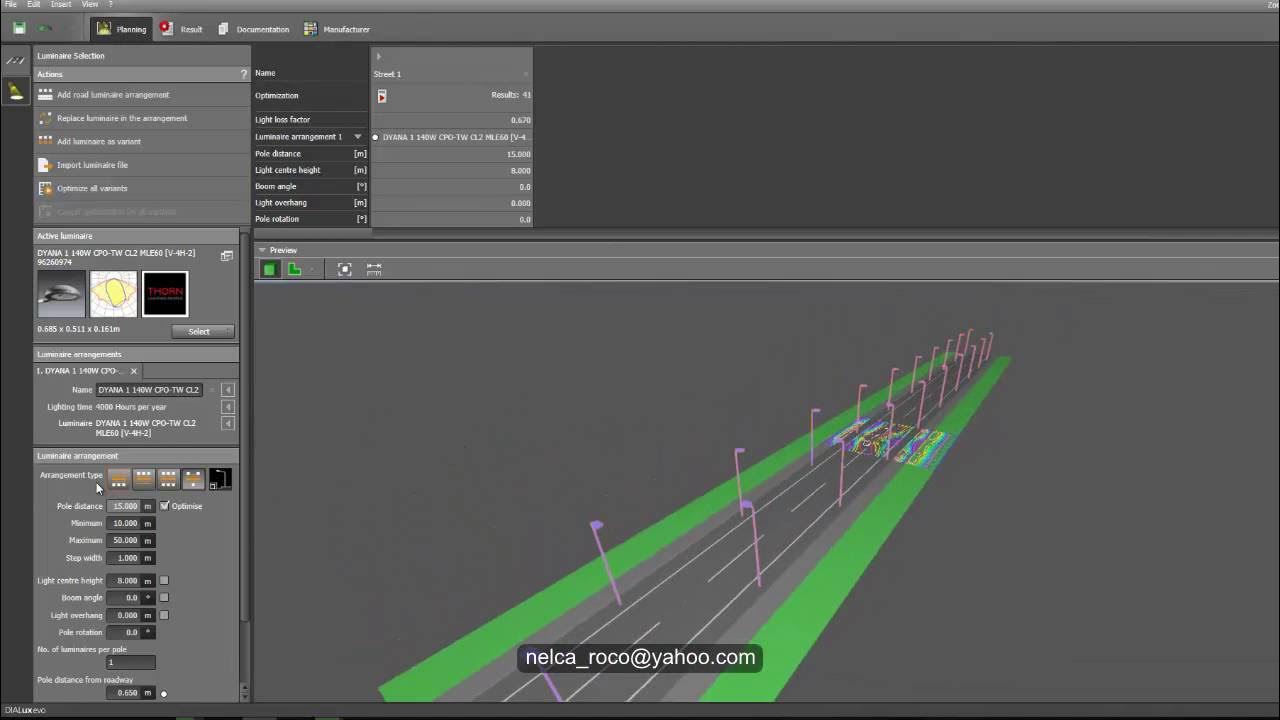
Dialux evo - How to do Street Lighting Design Calculation1
Fusion 360 beginner's Exercise #1 - Fusion 360 tutorial
Fusion 360 beginner's Exercise #10 - Fusion 360 tutorial

Submitting Design Requests via KIMP360
Fusion 360 beginner's Exercise #8 - Fusion 360 tutorial
5.0 / 5 (0 votes)
