Breadboard - Explained in Depth
Summary
TLDRIn this video, the instructor explains how breadboards are used to quickly test and prototype electronic circuits without soldering. The video covers key concepts such as how breadboards make electrical connections, the use of multimeters to check continuity, and the difference between series and parallel circuits. The instructor also demonstrates the importance of component polarity, the role of capacitors, and how to avoid short circuits. Viewers are encouraged to practice their breadboard skills with hands-on projects, like building an SpO2 monitor, to reinforce their understanding of basic electronics.
Takeaways
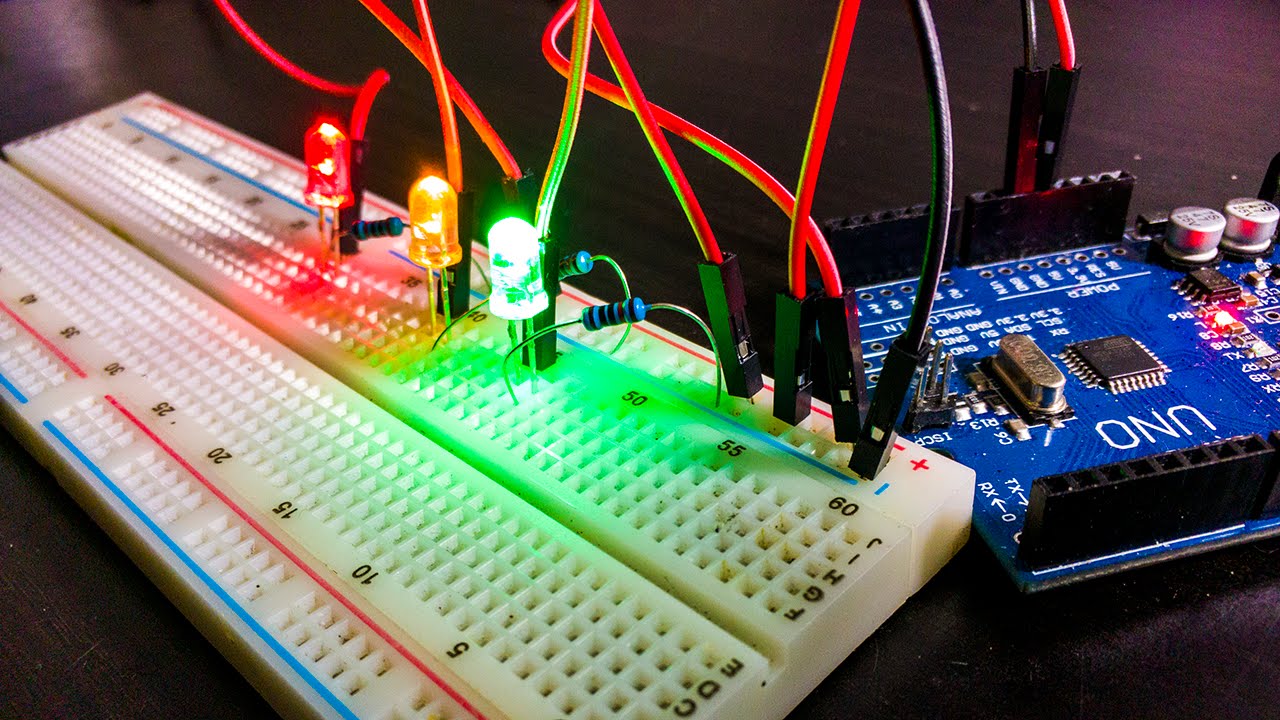
- 😀 A breadboard is a tool used to quickly build and test electronic circuits without soldering.
- 😀 The name 'breadboard' comes from early uses of actual breadboards (wooden boards) to test circuits.
- 😀 A multimeter in continuity mode is used to check if two points on a breadboard are electrically connected.
- 😀 Breadboards have power rails (bus strips) on the sides for easy power distribution across the circuit.
- 😀 The center rows of the breadboard are split into two halves, meaning they aren't connected across different rows.
- 😀 Jumper wires are used to connect points that are not directly connected on the breadboard.
- 😀 When building a circuit, ensure that components like LEDs and capacitors are placed with the correct polarity.
- 😀 In a series circuit, components are connected one after another, ensuring current flows sequentially.
- 😀 Capacitors can store charge and continue to power a circuit for a short time after the main power is removed.
- 😀 A short circuit occurs when current bypasses intended components (like a resistor), potentially damaging the circuit.
- 😀 Always ensure that resistors are in series with components like LEDs to avoid overloading and destroying them.
Q & A
What is the purpose of a breadboard?
-A breadboard is used to quickly build and test electronic circuits without soldering, allowing for easy connections and modifications during testing.
Why is it called a 'breadboard'?
-The term 'breadboard' comes from the historical practice of using a wooden board, often a breadboard, to prototype electrical circuits.
How does a breadboard create electrical connections?
-A breadboard connects various components by utilizing internal metal strips that create paths for electrical current to flow between points on the board.
What does the continuity mode on a multimeter help with when testing a breadboard?
-Continuity mode on a multimeter helps check for low resistance connections, indicating that two points on the breadboard are electrically connected.
What are the power rails on a breadboard, and how are they used?
-The power rails (also called bus strips) are the long horizontal strips on the sides of the breadboard that are electrically connected, often used for distributing power (e.g., ground or supply voltage) across the board.
Are the rows in the center of a breadboard connected to each other?
-No, the rows in the center of the breadboard are not connected to each other. Each row has five connected points, but the rows are isolated from one another unless connected by jumper wires.
How can two different rows on the breadboard be electrically connected?
-Two different rows can be connected by using jumper wires, which allow you to bridge the gap between isolated rows or different parts of the circuit.
What is the significance of the polarity of components like LEDs and capacitors on the breadboard?
-Components like LEDs and capacitors have specific polarities, meaning they must be connected in a certain way. The cathode (short leg) of an LED or capacitor should be connected to the lower potential side of the circuit.
What happens when you create a short circuit on the breadboard?
-A short circuit occurs when current flows through an unintended path, bypassing components like resistors, which can overload the circuit and potentially damage components, such as an LED, due to excess current.
Why is it important not to have both legs of a resistor in the same row of a breadboard?
-Placing both legs of a resistor in the same row creates a parallel path, potentially causing a short circuit. The resistor needs to be in series with other components to limit current flow properly.
Outlines

此内容仅限付费用户访问。 请升级后访问。
立即升级Mindmap

此内容仅限付费用户访问。 请升级后访问。
立即升级Keywords

此内容仅限付费用户访问。 请升级后访问。
立即升级Highlights

此内容仅限付费用户访问。 请升级后访问。
立即升级Transcripts

此内容仅限付费用户访问。 请升级后访问。
立即升级浏览更多相关视频
How to use a BreadBoard - Electronics Basics 10

Basic Electronics for Beginners in 15 Steps

All electronic components names, functions, testing, pictures and symbols - smd components

Beginner Electronics - 10 - Bread Boards

Electrical Engineering: Basic Laws (3 of 31) Open and Short Circuits
How to Make an Automatic Emergency Light || Power Failure Backup Light
5.0 / 5 (0 votes)
