Testirajte dodjelu sučelja

Edukacije Brček
22 Jun 202404:32

Summary

TLDRIn this video, the presenter demonstrates how to verify IP addresses assigned to switches S1 and S2. First, they connect a console cable to switch S1, use terminal commands to check the interface status, and activate VLAN 1 by using the 'no shutdown' command. The process is repeated for switch S2, where the IP address is assigned manually before activating the interface. The presenter ensures both switches have functioning IP addresses and active interfaces, providing a step-by-step guide for network configuration verification.

Takeaways

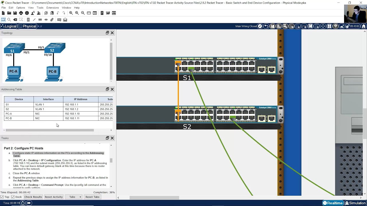
  • 🔌 The task involves verifying that IP addresses 192.168.1.2 and 192.168.1.3 are assigned to switches S1 and S2 respectively.
  • 🔧 These IP addresses should be assigned to the default Switched Virtual Interface (SVI), specifically interface VLAN 1.
  • 💻 The process starts by connecting a console cable from PC A to switch S1’s console port.
  • 📟 On PC A, a terminal emulation program is launched to access the command line interface (CLI) of switch S1.
  • 🖥️ The 'enable' command is used to switch to privileged exec mode, followed by the 'show IP interface brief' command to check interface details on switch S1.
  • ⚠️ The interface VLAN 1 on switch S1 is found to be in a 'shutdown' state, requiring the 'no shutdown' command to activate it.
  • ✅ After issuing the 'no shutdown' command, the state of interface VLAN 1 on S1 changes to 'up'.
  • 🔗 The same process is followed on switch S2, starting with connecting a console cable from PC B to switch S2’s console port.
  • 🌐 Switch S2’s interface VLAN 1 initially has no IP address, so the IP address 192.168.1.3 and subnet mask are assigned.
  • 📈 The interface VLAN 1 on switch S2 is also activated using the 'no shutdown' command, confirming both IP assignment and activation.

Q & A

  • What is the purpose of assigning IP addresses to switches S1 and S2?

    -The purpose of assigning IP addresses to switches S1 and S2 is to enable remote management and monitoring of the switches. The IP addresses are assigned to the default Switched Virtual Interface (SVI) or interface VLAN 1 on both switches.

  • How do you connect the console cable between PCA and Switch S1?

    -To connect the console cable, first click on the console cable in the simulation software, then click on PCA and connect it to the RS232 serial port. After that, stretch the cable to Switch S1 and connect it to the console port.

  • What command is used to switch to privileged exec mode on Switch S1?

    -The command 'enable' is used to switch to privileged exec mode on Switch S1.

  • What does the 'show IP interface brief' command display?

    -The 'show IP interface brief' command displays a summary of all interfaces on the switch, including their IP addresses, status (up/down), and protocol state.

  • Why was interface VLAN 1 on Switch S1 in a 'shutdown' state initially?

    -Interface VLAN 1 was in a 'shutdown' state because it had been administratively disabled. This is indicated by the 'administratively down' status, meaning the interface was not active.

  • What command is used to bring interface VLAN 1 up on Switch S1?

    -The 'no shutdown' command is used to bring interface VLAN 1 up on Switch S1, changing its state from 'administratively down' to 'up'.

  • How can you verify that interface VLAN 1 is up after running the 'no shutdown' command?

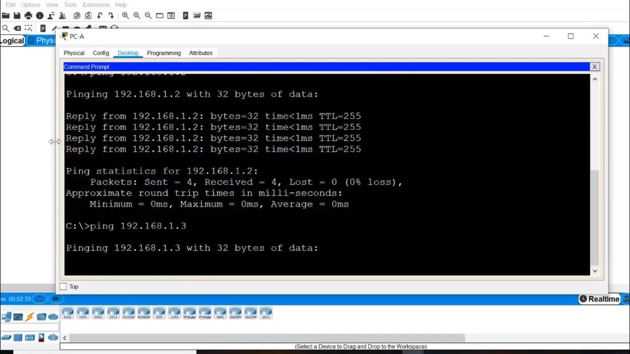
    -You can verify that interface VLAN 1 is up by reissuing the 'show IP interface brief' command. The state of the interface should now show 'up' for both the physical state and the line protocol.

  • What was the issue with interface VLAN 1 on Switch S2, and how was it resolved?

    -The issue with interface VLAN 1 on Switch S2 was that it had not yet been assigned an IP address. This was resolved by entering interface configuration mode and assigning it the IP address '192.168.1.3' followed by using the 'no shutdown' command to bring the interface up.

  • What is the subnet mask used when assigning the IP address to interface VLAN 1 on Switch S2?

    -The subnet mask used when assigning the IP address to interface VLAN 1 on Switch S2 is the default '255.255.255.0'.

  • How can you confirm that the IP address has been successfully assigned to interface VLAN 1 on Switch S2?

    -You can confirm that the IP address has been successfully assigned by running the 'show IP interface brief' command and verifying that interface VLAN 1 now has the assigned IP address '192.168.1.3' and its status is 'up'.

Outlines

00:00

🔌 Connecting and Verifying IP Assignment on Switch S1

The video starts by explaining how to verify the IP addresses assigned to switches S1 and S2. The IP addresses 192.168.1.2 and 192.168.1.3 should be assigned to the default interface VLAN 1 on both switches. The user begins by connecting a console cable from PCA to switch S1 and opens a terminal emulator to access the command-line interface. After entering privileged EXEC mode with the 'enable' command, the user issues the 'show IP interface brief' command to view the interfaces on S1. Interface VLAN 1 has the IP address 192.168.1.2, but it is in an administratively down state, which requires further steps to activate.

⚙️ Enabling VLAN 1 on Switch S1

To resolve the down state of VLAN 1 on switch S1, the user enters global configuration mode and then interface configuration mode for VLAN 1. They use the 'no shutdown' command to bring the interface up. After activating the interface, a message confirms that the interface's status has changed to 'up.' The user returns to privileged EXEC mode and reissues the 'show IP interface brief' command to confirm that VLAN 1 is now up and running, both physically and in terms of line protocol.

🔗 Verifying Configuration on Switch S2

Next, the video moves on to verifying the switch virtual interface configuration on S2. The user connects a console cable from PCB's serial port to the console port of switch S2, opens a terminal emulation program, and enters privileged EXEC mode. By issuing the 'show IP interface brief' command, they observe that VLAN 1 has not yet been assigned an IP address on S2.

💻 Assigning IP Address and Activating VLAN 1 on Switch S2

To assign an IP address to VLAN 1 on S2, the user enters global configuration mode, then interface configuration mode, and assigns the IP address 192.168.1.3 with its subnet mask using the 'IP address' command. The 'no shutdown' command is used to activate the interface, and a message confirms that the interface has come up. The user returns to privileged EXEC mode, reissues the 'show IP interface brief' command, and confirms that VLAN 1 is now assigned the correct IP address and its state is 'up and up.'

Mindmap

Keywords

💡IP Address

An IP address is a numerical label assigned to devices on a network to facilitate communication. In the video, IP addresses 192.168.1.2 and 192.168.1.3 are assigned to switches S1 and S2 respectively, allowing them to be uniquely identified within the network. This step is essential for verifying connectivity and configuration between network devices.

💡Switch

A switch is a networking device that connects devices within a network and forwards data based on MAC addresses. In this video, two switches, S1 and S2, are being configured. Each switch is assigned a unique IP address to its interface VLAN 1, ensuring they can communicate and be managed within the network.

💡VLAN 1

VLAN 1 refers to the default Virtual Local Area Network interface on switches. It is a virtual network that allows multiple devices to be part of a single broadcast domain. In the video, both switches have their VLAN 1 interfaces configured with specific IP addresses to enable network communication and management.

💡Console Cable

A console cable is a physical cable used to connect a computer to the console port of a networking device like a switch or router for configuration. In the video, the user connects the console cable from the PC (PCA and PCB) to switches S1 and S2 to access their command line interfaces for configuration.

💡Command Line Interface (CLI)

The Command Line Interface (CLI) is a text-based user interface used to interact with network devices. In the video, the user uses the CLI to issue commands such as 'enable' and 'show IP interface brief' on the switches to configure and verify the status of the network interfaces.

💡Global Configuration Mode

Global Configuration Mode is a mode in the CLI that allows users to make changes that affect the entire device. In the video, the user enters Global Configuration Mode to configure settings on both switches, such as activating the VLAN interface and assigning IP addresses.

💡No Shutdown Command

The 'no shutdown' command is used in the CLI to activate a network interface that is administratively down. In the video, this command is issued on both switches’ VLAN 1 interfaces to bring them into an 'up' state, enabling communication on the network.

💡Show IP Interface Brief Command

The 'show IP interface brief' command is used to display the IP addresses and the status of all interfaces on a network device. In the video, this command is issued on both S1 and S2 switches to verify the status of the VLAN 1 interfaces and ensure they are configured correctly.

💡Interface VLAN 1

Interface VLAN 1 refers to the specific virtual interface assigned to VLAN 1 on a switch. In the video, both switches S1 and S2 have their Interface VLAN 1 assigned with unique IP addresses (192.168.1.2 and 192.168.1.3), and the status of these interfaces is checked to confirm they are active and up.

💡Privilege Exec Mode

Privilege Exec Mode is a mode in the CLI that grants a user higher-level administrative access to execute configuration and monitoring commands on network devices. In the video, the user enters Privilege Exec Mode by typing 'enable,' allowing them to run commands to verify and configure network interfaces.

Highlights

Verification of IP addresses assigned to switches S1 and S2 is required.

The IP addresses 192.168.1.2 and 192.168.1.3 should be assigned to interface VLAN 1 on switches S1 and S2.

A console cable is connected from PCA to switch S1 via the RS232 serial port to verify configuration.

Terminal emulation program is launched on PCA to access the command line interface (CLI) on switch S1.

In switch S1's CLI, the command 'enable' is used to switch to privilege exec mode.

The 'show IP interface brief' command is issued to examine switch S1 interfaces.

Interface VLAN 1 on switch S1 has the IP address 192.168.1.2 but is in a 'shutdown' state.

To activate the interface, the 'no shutdown' command is used in global configuration mode.

After activation, the interface state changes to 'up' and 'up,' confirming it is operational.

Console cable is now connected from PCB to switch S2 to verify its configuration.

Terminal emulation is used again to access the CLI of switch S2.

The 'show IP interface brief' command reveals that interface VLAN 1 on S2 has not been assigned an IP address yet.

The IP address 192.168.1.3 is assigned to interface VLAN 1 on switch S2 using the 'IP address' command.

The 'no shutdown' command is executed to bring interface VLAN 1 on S2 to 'up' state.

After reissuing the 'show IP interface brief' command, VLAN 1 on switch S2 is verified to be 'up' and has the correct IP address of 192.168.1.3.

Transcripts

play00:01

in this video I need to verify that the

play00:03

IP addresses 1

play00:07

192.168.1.2 and

play00:10

192.168.1.3 have been assigned to

play00:12

switches S1 and S2 these IP addresses

play00:16

should have been assigned to the default

play00:18

switched virtual interface or interface

play00:21

VLAN 1 on both switches in order to

play00:24

verify this I will first connect a

play00:27

console cable from PCA into switch S one

play00:30

I click on the console cable I click on

play00:34

PCA and connect it to the rs232 seral

play00:38

port and then stretch the cable to

play00:40

switch S1 and connect it to the console

play00:44

Port now I'll click on

play00:46

PCA click on the terminal emulation

play00:49

program and click okay to accept the

play00:52

default configuration settings and this

play00:54

should take me to the command line

play00:56

interface on switch S1

play01:00

from here I'll type enable to switch to

play01:02

privilege exec mode and then I can issue

play01:05

the show IP interface brief command to

play01:09

examine the interfaces on switch S1 I

play01:13

will need to press the space bar in

play01:15

order to view the full display at the

play01:17

end of the output you can see interface

play01:20

VLAN 1 and it has an IP address of

play01:26

192.168.1.2 however if you look in this

play01:28

column you'll see that the state of the

play01:30

interface is administratively down this

play01:33

means that that interface is in a

play01:35

shutdown State you can also see that the

play01:38

line protocol of the interface is also

play01:40

down in order to correct that I first

play01:43

need to go into Global configuration

play01:46

mode then I'll go into interface

play01:49

configuration mode for interface VLAN 1

play01:53

and I will issue the no shutdown command

play01:56

which will activate the interface and

play01:58

you can see that I'm immediately

play01:59

presenting with a message that indicates

play02:01

that the interface has changed its state

play02:03

to up from here I press enter contrl c

play02:07

and enter again to return to privilege

play02:09

exec mode and now I can use the up arrow

play02:12

on my keyboard to reissue the show IP

play02:15

interface brief command and then verify

play02:18

that now the state of that interface is

play02:21

up and up meaning that it is physically

play02:24

up and the line protocol is now up next

play02:28

I will verify the switch virtual

play02:30

interface configuration on S2 to do that

play02:34

I will connect a console cable from

play02:37

pcb's serial Port into the console Port

play02:42

of switch

play02:44

S2 click on PCB go to the desktop tab

play02:49

open the terminal emulation program

play02:52

accept the default configuration

play02:54

settings and then that should take me to

play02:57

the command line interface of switch

play03:03

S2 from here I will enter privilege

play03:07

exact mode and then issue the show IP

play03:11

interface brief command to examine the

play03:15

interfaces on switch S2 you can see at

play03:18

the end of the output we have interface

play03:20

VLAN 1 and at this point it has not yet

play03:24

been assigned an IP address to assign an

play03:27

IP address I will first enter Global

play03:30

configuration mode and then interface

play03:33

configuration mode for interface VLAN 1

play03:37

and I'll assign the address by using the

play03:39

IP address command and give it the

play03:42

address 1

play03:45

192.168.1.3 followed by its subnet

play03:49

mask in order to activate the interface

play03:52

I will use the no shutdown command or no

play03:55

shut for short and you can see that the

play03:57

interface has changed its state to up

play04:00

from here I will do contrl c and press

play04:04

enter to return to privilege exec mode

play04:06

and again reissue that show IP interface

play04:10

brief command to examine the interfaces

play04:13

press my space bar and at the end of the

play04:16

output I can see that interface VLAN 1

play04:20

has been assigned the IP address

play04:25

192.168.1.3 and the state of the

play04:27

interface is up and up

Rate This

5.0 / 5 (0 votes)

相关标签
IP verificationSwitch configurationVLAN setupConsole connectionNetwork troubleshootingCLI commandsCisco switchesNetworking basicsInterface activationIT tutorials
您是否需要英文摘要?