How Power Transformers work ? | Epic 3D Animation #transformers
Summary
TLDRThis video explores the workings of power transformers, key devices in electrical energy transmission and distribution. It explains the basic principles of transformers, including electromagnetic induction, mutual induction, and the difference between step-up and step-down transformers. The video also covers transformer components such as windings, laminated cores, and bushings, and discusses efficiency improvements like minimizing eddy currents. Additionally, the video explains transformer types, the importance of transformer oil, and the role of tap changers in adjusting voltage levels during variable loads.
Takeaways
- ⚡ Transformers revolutionized the field of electrical energy transmission and distribution by enabling constant voltage AC supply systems.
- 🔌 Transformers work on the principle of electromagnetic induction, which occurs when a changing magnetic flux induces voltage in a nearby coil.
- 🔄 Transformers are static machines that increase or decrease voltage levels of an AC supply with a corresponding change in current.
- 💡 The primary winding of a transformer is connected to the supply, while the secondary winding delivers the output voltage.
- 🛠️ Transformers use ferromagnetic cores to improve efficiency by providing a low reluctance path for magnetic flux and minimizing leakage flux.
- 🔥 Laminated cores are employed in transformers to reduce energy losses caused by eddy currents, improving overall efficiency.
- 🔋 Step-up transformers increase voltage while lowering current, whereas step-down transformers decrease voltage and raise current.
- 🌐 Transformers do not change the frequency of the AC supply; the input and output frequency remain the same.
- ⚙️ On-load tap changers allow transformers to adjust voltage ratios to maintain stable output under varying load conditions.
- 🌡️ Transformers are filled with insulating oil for cooling and insulation, and a conservator tank is used to store excess oil.
Q & A
What is the primary function of a transformer?
-A transformer is used for increasing or decreasing the voltage levels of an AC supply with a corresponding change in current. It transfers electrical energy from one circuit to another through mutual induction.
Why do transformers not incur frictional or windage losses?
-Transformers do not have any moving parts, except for the on-load tap changer (OLTC) and motor drive unit, which minimizes frictional or windage losses. This makes them one of the most efficient electrical machines.
What principle does a transformer operate on?
-A transformer operates on the principle of mutual induction. When an alternating current (AC) flows through the primary coil, it produces a varying magnetic field that induces a voltage in the secondary coil.
Why doesn't electromagnetic induction work with a DC supply in transformers?
-Electromagnetic induction requires a change in magnetic flux to induce voltage. Since a DC supply generates a constant magnetic field without flux changes, no voltage is induced in the secondary coil.
What is the purpose of the transformer core?
-The transformer core provides a low reluctance path for the magnetic flux between the primary and secondary windings, making the transfer of electrical energy more efficient.
What are eddy currents and how are they minimized in a transformer?
-Eddy currents are loops of electric current induced in the transformer core due to the changing magnetic flux. They cause energy loss in the form of heat. To minimize them, laminated cores made of thin, insulated sheets are used.
What is the difference between a step-up and step-down transformer?
-A step-up transformer increases the voltage from the primary to the secondary winding, while a step-down transformer decreases the voltage from the primary to the secondary winding.
What role do tappings play in a transformer?
-Tappings are connection points along the winding that allow access to different portions of the coil, enabling voltage adjustments. They are used to fine-tune the transformer’s output voltage.
Why are power transformers designed with a laminated core?
-Power transformers use a laminated core to reduce eddy current losses. The insulation between the thin sheets of ferromagnetic material blocks the flow of eddy currents, enhancing efficiency.
What is the difference between single-phase and three-phase transformers?
-Single-phase transformers operate on single-phase AC supply and are typically used for low power applications like home electricity. Three-phase transformers operate on a three-phase AC supply and are used for high power applications like industrial power distribution.
Outlines

此内容仅限付费用户访问。 请升级后访问。
立即升级Mindmap

此内容仅限付费用户访问。 请升级后访问。
立即升级Keywords

此内容仅限付费用户访问。 请升级后访问。
立即升级Highlights

此内容仅限付费用户访问。 请升级后访问。
立即升级Transcripts

此内容仅限付费用户访问。 请升级后访问。
立即升级浏览更多相关视频
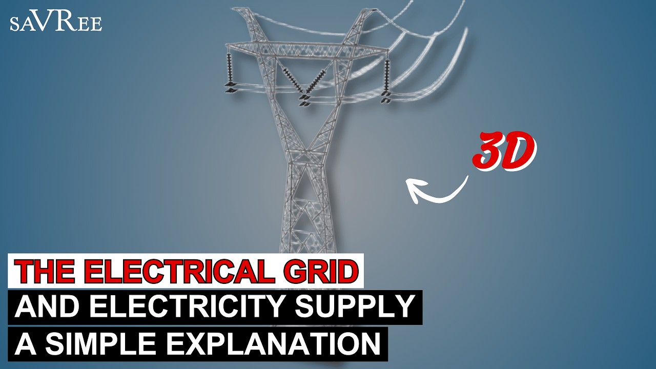
The Electrical Grid and Electricity Supply | A Simple Explanation

A física dos transformadores elétricos e suas aplicações indispensáveis
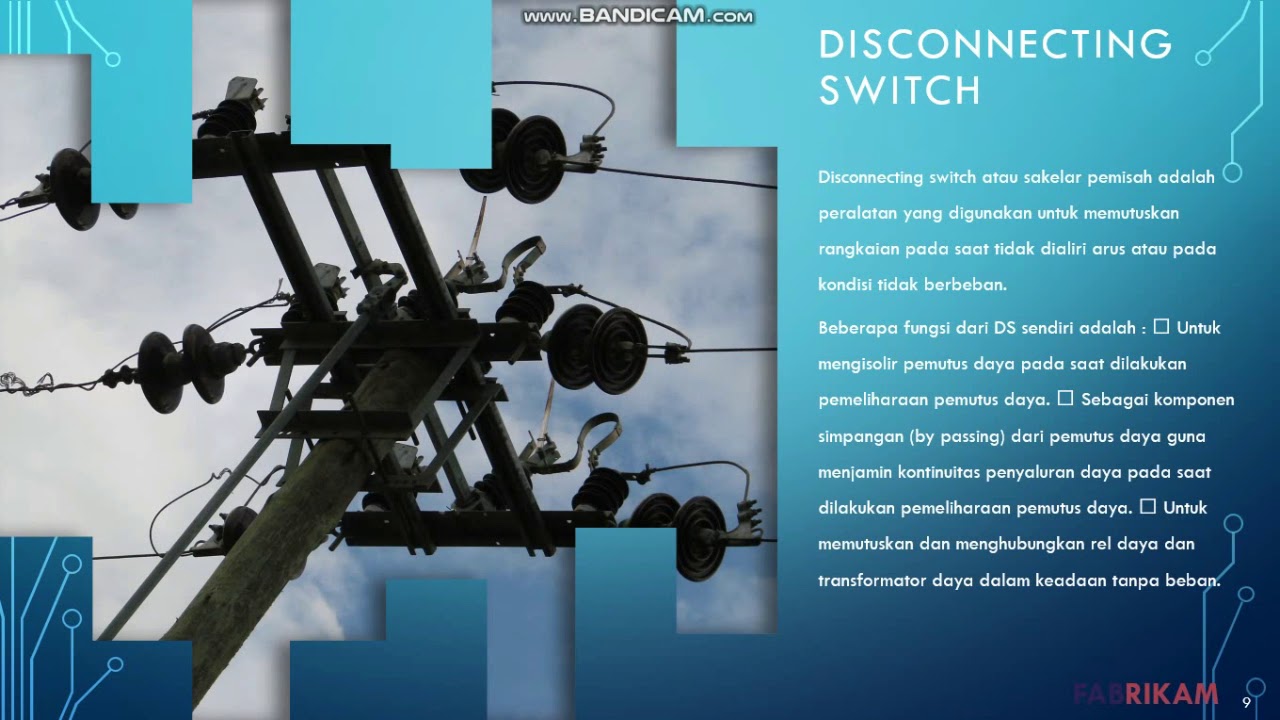
20 Jenis peralatan distribusi listrik
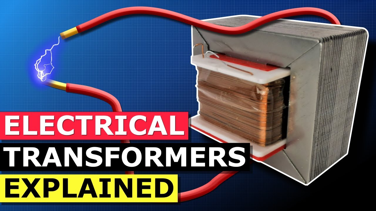
Transformers Explained - How transformers work
FISIKA Kelas 12 - Induksi Elektromagnetik: Generator & Transformator | GIA Academy

TOPIC 2: ELECTRICAL GENERATION AND TRANSMISSION
5.0 / 5 (0 votes)
