How Shell and Tube Heat Exchangers Work (Engineering)
Summary
TLDRThis video offers an insightful exploration into shell and tube heat exchangers, detailing their structure, operation, and the distinction between single and multi-pass models. It highlights the advantages of these heat exchangers, such as cost-effectiveness, simple maintenance, and suitability for high pressures and temperatures, while also addressing their limitations, including lower efficiency and inflexibility in cooling capacity compared to plate heat exchangers.
Takeaways
- 🔧 Shell and tube heat exchangers are crucial in engineering for transferring heat between two fluids.
- 🏭 The video provides an overview of the main components, design features, advantages, and disadvantages of shell and tube heat exchangers.
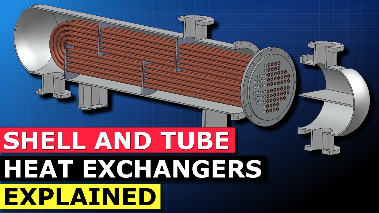
- 🌐 The shell, which acts as a pressure vessel, houses the tubes through which one fluid flows, while the other fluid flows in the shell.
- 💧 Both the tube side fluid and the shell side fluid play integral roles in heat exchange, with their flows being designed for maximum efficiency.
- 🔄 The video explains different types of flow designs, including counter flow, cross flow, and parallel flow, each with its own efficiency and application.
- 🛠️ Maintenance of shell and tube heat exchangers is relatively straightforward due to their simple design and the ease of accessing the tubes.
- 💹 They are cost-effective and suitable for high pressures and temperatures, which are advantages over plate heat exchangers.
- 🚫 However, they are less efficient than plate heat exchangers, require more space, and do not allow for easy adjustments to cooling capacity.
- 🔬 The video uses 3D models to illustrate the internal structure and flow paths, enhancing understanding of how these heat exchangers operate.
- 📚 For further learning, the video suggests visiting the provided website for articles and interactive 3D models, as well as considering online courses for deeper knowledge.
Q & A
What is the main topic of the video?
-The main topic of the video is the shell and tube heat exchanger, discussing its components, design features, advantages, disadvantages, and how it works.
What are the two main fluids involved in a shell and tube heat exchanger?
-The two main fluids involved are the tube side fluid and the shell side fluid, which flow through the tubes and the shell respectively.
What is the purpose of the shell in a shell and tube heat exchanger?
-The shell serves as a pressure vessel that houses the tubes and provides a space for the shell side fluid to flow and exchange heat with the tube side fluid.
Why are baffles used in a shell and tube heat exchanger?
-Baffles are used to create a path for the shell side fluid to flow around the tubes, promoting turbulent flow which enhances heat transfer and helps prevent fouling.
What is the function of tube sheets in a shell and tube heat exchanger?
-Tube sheets are used to hold the tubes in position and seal the inside of the shell to ensure the shell side fluid stays within the space between the two tube sheets.
What is the purpose of turbulators or tube inserts in the tubes?
-Turbulators or tube inserts are used to create turbulent flow within the tubes, which increases the heat transfer capacity and helps keep the tubes clean by reducing the buildup of deposits.
What is the difference between a single pass and a multi-pass heat exchanger?
-In a single pass heat exchanger, the fluid flows through the tubes once before exiting. In a multi-pass heat exchanger, the fluid makes multiple passes over the tubes, enhancing heat transfer.
What is a U-tube shell and tube heat exchanger?
-A U-tube shell and tube heat exchanger is a design where the tubes are bent into a U-shape, allowing for expansion and contraction without stressing the tube sheets.
What are the advantages of shell and tube heat exchangers over plate heat exchangers?
-Shell and tube heat exchangers are generally cheaper, simpler to maintain, suitable for higher pressures and temperatures, have less pressure drop, and are less prone to fouling compared to plate heat exchangers.
What are the disadvantages of shell and tube heat exchangers compared to plate heat exchangers?
-Shell and tube heat exchangers are less efficient, require more space for maintenance, and do not allow for easy adjustment of cooling capacity like plate heat exchangers do.
What type of flow design is the most efficient for a heat exchanger?
-Counter flow design is the most efficient type of flow for a heat exchanger, where the tube side fluid and shell side fluid flow in opposite directions.
Outlines
🔧 Introduction to Shell and Tube Heat Exchangers
The narrator, John, introduces the topic of shell and tube heat exchangers, explaining that the video will cover the main components, design features, advantages, disadvantages, and the working mechanism of these devices. He clarifies that the video is intended for both those who are familiar with the subject and those who are new to it. John then demonstrates the external appearance of a standard shell and tube heat exchanger, highlighting the shell, which acts as a pressure vessel, and the four main connections for fluid flow. He explains the concept of tube side and shell side fluids, and their respective flow paths within the heat exchanger. The video uses a cross-sectional view to illustrate the internal structure, including the straight tubes for the tube side fluid and the baffles for directing the shell side fluid. John also touches on the broader concept of 'fluids' being applicable to both liquids and gases.
🛠 Components and Design of Shell and Tube Heat Exchangers
This section delves into the detailed components of the shell and tube heat exchanger, starting with the tube sheets that hold the tubes in place and seal the shell to contain the shell side fluid. Baffles are introduced as structural elements that support the tubes and maintain their alignment. The concept of turbulators or tube inserts is explained, which are designed to induce turbulent flow within the tubes to enhance heat transfer and prevent fouling. The video then shifts focus to the shell side fluid, detailing how it flows around the tubes, facilitated by baffles, to maximize heat exchange and minimize the risk of deposits. A different design, the U-tube shell and tube heat exchanger, is presented, highlighting the U-shaped tubes as a variation from the straight tubes seen earlier. The concept of single pass versus multi-pass heat exchangers is introduced, explaining how the number of times the fluids pass through the exchanger affects its design and efficiency.
🌡️ Flow Designs and Efficiency in Heat Exchangers
The video discusses various flow designs in heat exchangers, including counter flow, cross flow, and parallel flow, each with its own efficiency and application considerations. Counter flow is described as the most efficient design due to the opposing flow directions of the two fluids, which maximizes heat transfer. In contrast, parallel flow and cross flow designs are explained, with the latter involving fluids flowing at a 90-degree angle to each other. The narrator then compares shell and tube heat exchangers with plate heat exchangers, highlighting the advantages such as lower cost, simplicity, suitability for high pressures and temperatures, and ease of maintenance and leak detection. Disadvantages are also mentioned, including lower efficiency, larger space requirements, and the inability to adjust cooling capacity without major modifications.
📚 Conclusion and Further Learning Opportunities
In the concluding part, the narrator directs viewers to the website for more detailed information on shell and tube heat exchangers through associated articles and 3D models. He also promotes the platform's online video courses covering a wide range of engineering topics, including heat exchangers, and offers a discount coupon for viewers interested in these courses. The video ends with a call to action for viewers to share, like, and subscribe to the YouTube channel for more content.
Mindmap
Keywords
💡Shell and Tube Heat Exchanger
💡Tube Side Fluid
💡Shell Side Fluid
💡Baffles
💡Tube Sheets
💡Turbulators or Tube Inserts
💡U-Tube Shell and Tube Heat Exchanger
💡Single Pass and Multi-Pass
💡Counter Flow, Cross Flow, and Parallel Flow
💡Advantages and Disadvantages
Highlights
Introduction to shell and tube heat exchangers, suitable for those new to the topic or those looking to reinforce their knowledge.
Exploration of the main components that constitute a shell and tube heat exchanger.
Design features of shell and tube heat exchangers, including their advantages and disadvantages.
Visual demonstration of how a shell and tube heat exchanger operates.
Description of the shell as a pressure vessel and its role in fluid dynamics within the heat exchanger.
Explanation of the fluid flow paths for both the tube side and shell side fluids.
Detailed look at the tube side fluid's flow path, including its entry, travel through tubes, and exit.
Discussion on the shell side fluid's journey through baffles and its discharge.
Clarification that 'fluids' can refer to both liquids and gases in the context of heat exchangers.
Introduction to the tube bundle or stack and its role in holding tubes in position.
Explanation of how tube sheets, baffles, and tie rods contribute to the structural integrity of the heat exchanger.
Description of turbulators or tube inserts and their function in enhancing heat transfer and preventing tube fouling.
Analysis of the shell side fluid dynamics, including its path around the tubes and the importance of turbulent flow.
Presentation of a U-tube shell and tube heat exchanger design and its distinctive features.
Differentiation between single pass and multi-pass heat exchangers and their operational implications.
Discussion on counter flow, cross flow, and parallel flow designs and their efficiency.
Advantages of shell and tube heat exchangers such as cost-effectiveness, simplicity, and suitability for high pressures.
Disadvantages of shell and tube heat exchangers compared to plate heat exchangers, including efficiency and space requirements.
Invitation to access further resources and courses for deepening knowledge on heat exchangers.
Encouragement for viewers to engage with the content by sharing, liking, and subscribing.
Transcripts
- [Narrator] Hi, John here and welcome
to another exciting and interesting video
on engineering machinery.
Now, in this video we're gonna be talking
about the shell and tube heat exchanger.
Some of you might think you know a lot about
shell and tube heat exchanges
and that's fine.
Then you can watch this video
and it will just reinforce what you already know.
Some of you might not know anything
about shell and tube heat exchanges
and that's also fine
because you're going to learn a lot in this video.
We're gonna look at all of the main components
that make up a shell and tube heat exchanger.
I'm gonna show you some of its design features,
its advantages and disadvantages
and I'm also gonna show you how it works.
So, let's get started.
Now, this is not how a shell and tube heat exchanger
normally looks in the workplace.
If it was, it would be a lot easier to understand
how it works.
So, let's reset the configurator tool for a moment
and now you can see the shell and tube heat exchanger
as it would normally be in the workplace.
There are different designs of variations
but this one here is quite standard.
So, let's start by looking at the outside
of the heat exchanger.
We've got the shell, it's a pressure vessel
which means it's gonna be pressurized
to match the fluid or the system pressure
that's flowing through it
or specifically flowing through the shell.
Sometimes people refer to the shell also as the housing.
We've also got a front and a rear of the heat exchanger.
Other than that, we've got four main connections
to the heat exchanger.
One, two, three and four.
We have two inlets and two outlets
because we have two fluids that are flowing into
and out of the heat exchanger.
This heat exchanger is called
a shell and tube heat exchanger
because it has a shell
and because within the shell there are some tubes.
Let's take a cross-section.
And we can now see exactly what's happening
inside the heat exchanger.
So, we have a tube side fluid.
The tube side fluid enters here and is discharged here.
We have a shell side fluid
which enters here and goes a long here
and it's discharged here.
The reason we call the tube side fluid the tube side fluid
is because it flows through tubes.
See it comes into the heat exchanger
and once it enters this area,
it has to flow through these tubes
because it's the only place it can go.
Once it flows through the tubes,
it's gonna get to the other end of the tubes.
These tubes are just straight tubes.
The fluid comes out on the lower section here
and re-enters in the top section here.
When the tube side fluid re-enters
through the top section of these tubes here,
it's gonna flow again in a straight line
to the opposite end of the heat exchanger
and it's gonna come out here
and then gonna be discharged or exit the heat exchanger
through the outlet.
That is the flow path of the tube side fluid.
The shell side fluid enters the heat exchanger here
and then it comes through
and it'll pass through a series of baffles
which we'll take a look at in a moment.
And it's gonna be discharged
through the shell side fluid outlet down here.
So, tube side fluid in on the lower left, along here,
straight flow, up, back the other way and then out.
Shell side fluid down through here,
passed all the baffles and then out
on the lower right-hand side.
Although, I refer to fluids in this video,
sometimes it's a little bit easier
to think of them as flowing mediums.
I say that because doctors say,
you should drink a lot of fluids
but realistically a fluid can also be a gas.
Let's have a look at the tube side flowing medium
in a bit more detail.
What I'm actually gonna do,
I'm gonna remove everything but the tubes
so that we can focus on those first.
So, here are our tubes.
The tubes are collectively known as a tube stack
or a tube bundle.
For example, the upper half of the tube bundle
would be all of the tubes above this row here
and the lower half of the tube bundle
would be all of the tubes below this row here.
So, that is our tube bundle or tube stack.
In order to hold the tube bundle
in the correct position,
we're gonna use baffles, tube sheets and also tie rods.
Let's add the tube sheets first.
These are our tube sheets the tube sheets.
The tube sheets are used to first,
hold the tubes in position
and secondly, to seal the inside of the shell
so that the shell side fluid stays within this space
between the two tube sheets.
So, here's one tube sheet,
sometimes known as the real tube sheet.
Here's the front tube sheet
and the shell side fluid is gonna remain in this space.
So, that's the pressure boundary for the shell side fluid.
We wanna fix the tubes in position
using more than just two anchor points.
So, we use baffles as well.
And the baffles just add some extra support
to help keep the tubes in alignment.
You'll also sometimes see tie rods.
And the tie rods are used to connect the tube sheets
or the baffles together
which again adds structural support to the tubes.
Within the tubes,
what you're actually going to have
are turbulators or tube inserts.
You'll push the tube inserts
into every one of these tube holes.
So, for example we'd push a tube insert in here
or a turbulator.
And that turbulator is gonna create turbulent flow.
This turbulent flow helps increase
the heat transfer capacity of the heat exchanger
and also it helps us keep the inside of the tubes clean.
We reduce the likelihood of deposits
building up on the inside of the tubes
because we have turbulent flow
rather than laminar flow.
So, that's everything related to the tube side fluid.
Let's load up some parts now.
So, we can have a look at the shell side fluid.
Now, we've already discussed the tubes
so I think we can remove those.
And we can see now exactly what's happening
with the shell side fluid.
The shell side fluid is entering through here.
It's going round the baffles
and then it is being discharged here.
We can see that around the tubes
there is space for the fluid to flow
because the tubes are not all directly next to each other.
There's a bit of a gap, you can see here.
If I come across, all of these gaps
where my mouse is going now
is where the shell side fluid is going to flow
around the tubes.
We wanna have turbulent flow,
the same as what we had in the tubes.
And in order to get that we use the baffles.
So, the shell side fluid comes in here,
flows around the tubes because of the baffles.
It will exchange heat with the fluid within the tubes
and then it's gonna drop out
of the shell side fluid outlet here.
Once again this turbulent flow increases
the heat transfer capacity of the heat exchanger
which makes it more efficient
but also helps us prevent or reduce
the likelihood of deposits building up
on the outside of the tubes.
Let's load up another 3D model,
so I can show you a slightly different design
of a shell and tube heat exchanger.
So, here is the first design
that I wanna show you.
It's slightly different from what we looked at before.
You can see that externally it looks pretty much the same
but if I show you the tubes
and we reverse that around.
You can see that the tubes themselves
are no longer just straight.
They're actually rounded into a u-shape.
This is actually called
a u-type shell and tube heat exchanger
or a u-tube shell and tube heat exchanger
which is slightly confusing.
But anyway, you can see that the tubes
have this u-shape.
Let's load up a more simple design
cause I just want to explain to you
what a one pass and a multi pass heat exchanger is.
So, here we have a heat exchanger
without a header or a bonnet.
And if we take away the shell,
in fact what we can do we can actually
just take a cross-section.
Can see that this time the tube side fluid
comes in here, flows through the tubes
and exits on this side here.
So, in on the right out on the left.
And what's interesting about this particular heat exchanger
is that the tube side fluid
represents a single pass of the heat exchanger.
You'll often hear people referring to heat exchangers
as either single or multi pass.
The shell side fluid has a multi pass design.
It's passing multiple times over the tubes.
The tube side fluid does not have a multi pass design
because it's traveling directly through the tubes
and then out.
If the tube side fluid was to come in from the right,
come out on the left and then go back around
and then exit on the right,
then this would be a multi pass design.
Because it too, would be passing through
the heat exchanger multiple times.
This heat exchanger would be described as a
multi pass heat exchanger
just because the shell side fluid
or one of the fluids is passing multiple times
over the other fluid.
If the shell side fluid came in from the top
and dropped out at the bottom with no baffles,
then the shell side fluid
would have a single pass design
and so with the tube side fluid.
And we would say, this is a single pass heat exchanger.
That's actually quite rare though.
You don't see that very often
because it's not very efficient.
If you have a look at steam condenses though,
you will see that design.
And generally, whenever you convert a vapor into a liquid
or whenever you're changing the state of something,
you'll often use a single pass design.
People also talk about counter flow, cross flow
and parallel flow.
This particular design is a counter flow design
because the tube side fluid enters on the right
and exits on the left.
And the shell side fluid enters on the left
and is discharged on the right.
So, they're flowing in opposite directions to one another,
right to left and left to right.
That is a counter flow design.
It is the most efficient type of flow design
you can have for a heat exchanger.
If the shell side fluid came in on the right
and exited on the left
then we'd have a parallel flow design
because both the tube side fluid
and the shell side fluid
are flowing from right to left.
If the shell side fluid came in at the top
and which discharged straight out of the bottom
this would be a cross flow design
because the fluids are flowing at a 90 degree angle
relative to each other.
So, different flow designs depend on
what you wanna use the heat exchanger for.
Let's have a talk now
about some of the advantages and disadvantages
associated with this type of heat exchanger.
When we talk about advantages and disadvantages
associated with the shell and tube heat exchanger,
we're often comparing it to the plate heat exchanger
because in the industrial world
we're either using plate heat exchangers
or shell and tube heat exchangers.
Normally, there are some other designs
but those two are the most dominant
within the industrial engineering world.
Now, shell and tube heat exchangers are relatively cheap.
They have a simple design
and they're quite easy to maintain.
They're also suitable for higher pressures and temperatures
compared to plate heat exchangers.
The pressure drop across shell and tube heat exchanger
is less than that of a plate heat exchanger.
It's also easy to find and isolate leaks in the tubes
compared to trying to find and isolated leak
in a plate heat exchanger.
Shell and tube heat exchangers also don't foul
as easily as plate heat exchangers
because they don't have the very fine clearances
that a plate heat exchanger has.
There are however some disadvantages.
They're less efficient than plate heat exchangers.
They also require more space to open
and remove the tubes.
And you can't increase the cooling capacity
of a shell and tube heat exchanger.
With the plate heat exchanger,
you can simply add more plates or remove plates
in order to vary the cooling capacity.
With the shell and tube type heat exchanger,
this is not possible.
If you wanna learn more about shell and tube heat exchangers
then I suggest you go to the website.
I'll put the link in the video description area
and you can read through one of our articles
which will tell you a little bit about
shell and tube heat exchangers
and discuss more of the topics
that we've covered in this video.
If you still wanna learn even more
about heat exchangers after that,
then you can check some of our other associated articles
within our 3D encyclopedia.
You can see here we have an associated article
for a plate heat exchanger.
If you want to access some free interactive 3D models,
then go to the website
and select any model from the 3D models menu
those highlighted green.
And if you wanna take your engineering knowledge
to the next level,
then check out some of that online video courses.
We have over 30 hours of video courses, currently online.
And they cover everything from valves to diesel engines
to pumps to heat exchangers.
I've pasted a discount coupon in the video description area
so if you do decide to purchase any courses,
then be sure to use that discount coupon.
If you like this video then please do share it
or like it on social media.
It really does help us out and we really appreciate it.
And don't forget to subscribe to our You Tube channel.
Thank you very much for your time.
浏览更多相关视频
5.0 / 5 (0 votes)