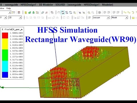
Rectangular Waveguide Design using HFSS
Summary
TLDRThis tutorial guides users through the process of designing a rectangular waveguide in HFSS software. The design steps include creating the 3D rectangular box, assigning excitations and boundary conditions, setting up the solution and frequency sweep, and running simulations. The script also covers how to visualize results, including field animations and magnitude plots, and how to generate reports for parameters like S11 and S21. By the end, users will have a complete understanding of how to design and analyze a rectangular waveguide in HFSS.
Takeaways
- 😀 Start a new project in HFSS by selecting 'New Project' and inserting a rectangular waveguide design.
- 😀 Set the dimensions for the rectangular waveguide: X = 22.86, Y = 0.6, Z = 60 (or 100, depending on the design).
- 😀 Position the waveguide at the center by setting X to -11 and Y to -5.08.
- 😀 Rotate the design and assign excitations by selecting the appropriate face of the waveguide.
- 😀 Use the 'WP' excitation on one face, then set the integration line to the midpoint of the edge.
- 😀 Assign the opposite excitation on the other side of the waveguide, ensuring both sides are excited.
- 😀 Apply 'Perfect E' boundary conditions to the remaining four faces of the waveguide.
- 😀 Set up the analysis by specifying a frequency of 10 GHz and adding a frequency sweep from 6 GHz to 15 GHz.
- 😀 Analyze the simulation and save your project once complete.
- 😀 View simulation results by selecting the 'E field' vector and visualizing the field animation in the waveguide.
- 😀 Generate a report that includes S-parameters (S11, S12, S21) for the waveguide design.
Q & A
What is the first step in creating a rectangular waveguide in HFSS?
-The first step is to open HFSS, create a new project, and insert a new design. Then, a rectangular box is selected for the waveguide structure.
What are the dimensions given for the rectangular waveguide?
-The dimensions for the rectangular waveguide are 22.86 for the X size, 0.6 for the Y size, and 60 or 100 for the Z size.
How are the positions of the waveguide defined?
-The positions are set relative to the dimensions. For the X position, it is half of the X size, so -11, and for the Y position, it is half of the Y size, so -5.08.
How is excitation applied to the waveguide in HFSS?
-Excitation is applied by selecting the appropriate face of the waveguide, right-clicking, and assigning the WP excitation. A new line is drawn, positioned at the midpoint of the opposite edge, and then finished.
How is the second excitation applied on the opposite face?
-The excitation is applied by selecting the opposite face, right-clicking to assign a new excitation, and defining the line with similar steps as the first excitation.
What boundary conditions are set for the waveguide?
-Perfect Electric Conductor (PEC) boundary conditions are applied to all four faces of the waveguide by selecting the faces and assigning the PEC boundary.
What is the frequency setup for the analysis in HFSS?
-In the analysis setup, the solution frequency is set to 10 GHz, and a frequency sweep is applied with a start frequency of 6 or 7 GHz and a step size of 1 GHz.
How is the simulation run in HFSS?
-Once the frequency sweep is set, right-click on the analysis and select 'Analyze All.' The simulation will process the data, and you can save the project afterward.
What visualization options are available after the simulation?
-After the simulation, you can view the electric field vectors (E-field) and animate how the wave travels through the waveguide. Additionally, you can plot the field magnitude on any selected edge.
How are the S-parameters reported in HFSS?
-The S-parameters (S11, S12, S21, and S22) can be viewed by right-clicking on the results and creating a report. A rectangular plot is generated showing the S-parameters at different frequencies.
Outlines

This section is available to paid users only. Please upgrade to access this part.
Upgrade NowMindmap

This section is available to paid users only. Please upgrade to access this part.
Upgrade NowKeywords

This section is available to paid users only. Please upgrade to access this part.
Upgrade NowHighlights

This section is available to paid users only. Please upgrade to access this part.
Upgrade NowTranscripts

This section is available to paid users only. Please upgrade to access this part.
Upgrade NowBrowse More Related Video
HFSS simulation of Rectangular Wave guide- Brief Theory, Concept of wave guide
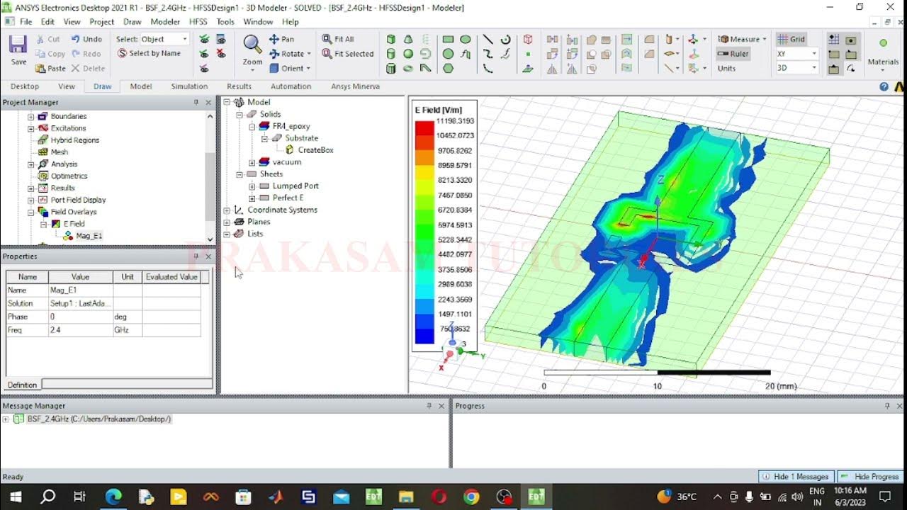
Band Stop Filter Using HFSS Software

Tutorial Software BLOCPLAN

Membuat Floor Slab (Pelat Lantai)

Basic Pembuatan SLD Pada Software ETAP || Single Line Diagram || Jaringan Distribusi ||

Solution of Wave Equation in Rectangular Waveguide
5.0 / 5 (0 votes)