Proteus Schematic - Sistem Kontrol Pompa Air #OTOMATIS
Summary
TLDRThis video showcases an automatic water pump control system designed by a mechanical engineering student using Proteus simulation software. The system uses two water level sensors (upper and lower) to manage the pump’s operation. When the water level is low, the pump turns on, and when the tank is full, the pump shuts off. The design involves components like transistors (BC547 and BC557), resistors, and a relay to regulate the circuit. The project highlights how a simple control system can automate water pumping efficiently, making it a useful solution for various applications.
Takeaways
- 😀 The video presents a project for an automatic water pump system using Proteus software for simulation.
- 😀 The system consists of two sensors (upper and lower) to monitor water levels in a tank.
- 😀 The pump automatically turns on when the lower sensor is triggered, indicating low water levels.
- 😀 The pump turns off when the upper sensor is activated, indicating the tank is full.
- 😀 The cycle repeats as the water level fluctuates between the two sensors, keeping the tank at a safe level.
- 😀 Key components used include transistors (BC547, BC557), resistors, a relay, and a 12V power supply.
- 😀 The relay acts as a switch to control the pump based on sensor inputs.
- 😀 The system is built and tested in Proteus, a circuit simulation tool, which helps visualize the functioning of the components.
- 😀 The sensors are represented as buttons in the simulation, with each button corresponding to a different sensor (upper and lower).
- 😀 The video concludes with the successful demonstration of the automatic water pump system turning on and off based on the water level detected by the sensors.
Q & A
What is the main objective of the automatic water pump control system described in the video?
-The main objective is to automate the operation of a water pump using sensors to detect water levels, ensuring that the pump turns on when the water level is low and turns off when it reaches a high level, preventing flooding or dry running.
What components are essential for building the automatic water pump control system?
-The key components include the water pump (acting as the motor), two water level sensors (upper and lower), BC547 and C557 transistors, resistors, a 12V power supply, and a DC voltmeter.
How do the sensors work in the system?
-The sensors detect the water level in the tank. The lower sensor triggers the pump to turn on when water is low, and the upper sensor turns the pump off once the water level reaches the desired height.
What role does the BC547 transistor play in the system?
-The BC547 transistor acts as a switch, controlling the power to the pump based on the signals received from the water level sensors. It ensures that the pump operates only when necessary.
Why is the pump turned off once the upper sensor is touched by water?
-The pump is turned off when the upper sensor is touched to prevent overfilling the tank, ensuring that the water level does not exceed the desired limit and cause flooding.
What happens when the water level drops and the bottom sensor is no longer in contact with water?
-When the water level drops and the bottom sensor is no longer in contact with water, the pump is activated again to refill the tank until the upper sensor is touched.
How is the water level monitoring system implemented in the Proteus application?
-In the Proteus application, the water level sensors are represented by buttons that simulate the physical sensors. These buttons provide the signals that control the pump and other system components.
What type of power supply is used for the system?
-The system uses a 12V power supply to operate the pump and other electrical components, such as the sensors and transistors.
How does the relay function in this control system?
-The relay acts as an electrical switch that connects or disconnects the pump's power circuit, based on the signals from the transistors and the water level sensors.
What is the purpose of the resistors in the circuit?
-The resistors are used to limit the current flow through the components, ensuring that the transistors and other electrical parts do not get damaged by excessive current.
Outlines

This section is available to paid users only. Please upgrade to access this part.
Upgrade NowMindmap

This section is available to paid users only. Please upgrade to access this part.
Upgrade NowKeywords

This section is available to paid users only. Please upgrade to access this part.
Upgrade NowHighlights

This section is available to paid users only. Please upgrade to access this part.
Upgrade NowTranscripts

This section is available to paid users only. Please upgrade to access this part.
Upgrade NowBrowse More Related Video

How To Build Automatic Water Dispenser Using Arduino
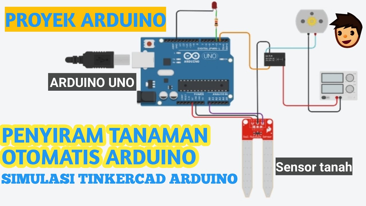
PROYEK ARDUINO PENYIRAM TANAMAN OTOMATIS DENGAN SENSOR KELEMBABAN TANAH SIMULASI TINKERCAD ARDUINO

TUTORIAL MEMBUAT PROJECT IOT SMART GARDEN / SMART FARMING DENGAN ESP32 #arduinoproject #esp32project
Sistem penyiraman tanaman otomatis esp8266 (BLYNK)
Cara Pasang Otomatis Pompa Air Dengan Kontaktor, Selector Switch dan Radar #pompaair

Automatismo cancello con PLC e chiusura automatica temporizzata simulazione CADeSIMU
5.0 / 5 (0 votes)