Cara Membuat Etiket/kepala gambar di Autocad
Summary
TLDRIn this tutorial, Misbah demonstrates how to create a standard label (etiket) in AutoCAD. The video walks through various commands such as Line, Offset, Trim, and Circle to build the label design. It explains how to add dynamic attributes like paper size, scale, date, and other essential details. The tutorial also covers the use of the Block Editor to group objects and manage editable attributes. By the end, viewers will learn how to create, edit, and finalize a label with all the necessary annotations and dimensions in AutoCAD, perfect for creating professional technical drawings.
Takeaways
- 😀 The video teaches how to create labels or drawing templates in AutoCAD, focusing on standard label creation.
- 😀 The process begins with creating a line and offsetting it to generate a series of parallel lines, each with specific measurements.
- 😀 Multiple offsets are applied to form the layout, using different measurements like 30, 40, 50, and 14 for various sections of the label.
- 😀 The 'Trim' command (TR) is used to cut unnecessary lines, helping to refine the design.
- 😀 Circles are added to the design as part of the label layout, with the use of the 'Circle' command to project them in specific locations.
- 😀 Center lines are created and adjusted using the 'Center Mark' tool, ensuring proper alignment of elements in the design.
- 😀 Text labels are added to the design, including paper size (A4), title, and other essential details like scale and drawing date.
- 😀 Copying and pasting text for repetition allows the user to efficiently add multiple descriptions, such as scale, date, and approval details.
- 😀 The video emphasizes the importance of using attributes (ATT) to handle dynamic text values like date and scale, ensuring the label can be updated easily.
- 😀 A final block is created to group all elements together, and a template for the label is formed with the specified paper size (A4, 297 x 210 mm).
Q & A
What is the main purpose of this video tutorial?
-The main purpose of the tutorial is to teach how to create a standard label or technical drawing in AutoCAD, which includes steps like drawing lines, adding text, and applying offsets.
Why does the tutorial mention that there are no strict rules for creating labels in AutoCAD?
-The tutorial emphasizes that different companies may have their own standards for label designs. The video aims to show a standard approach, but flexibility is allowed in the design based on specific requirements.
How does the tutorial suggest creating a label's boundary or main shape in AutoCAD?
-The tutorial begins by creating a line with a length of 185 units. Then, several offset commands are used to create concentric shapes, followed by trimming to refine the design.
What is the purpose of the 'offset' command in this tutorial?
-The 'offset' command is used to create parallel lines or shapes at a specified distance from the original object, helping in the design of concentric shapes and defining the boundaries for the label.
What should be done after creating the initial shapes and offsets?
-After creating the initial shapes, the tutorial guides users to trim excess parts of the shapes using the 'TR' (trim) command, ensuring the design is clean and precise.
What is the significance of adding a 'center mark' in the design?
-The 'center mark' is added to indicate the center of circles or other geometrical shapes. It helps in ensuring that the drawing is centered and aligned properly.
How does the tutorial show how to add text annotations?
-Text annotations are added using the 'T' (text) command, where the user types in various details such as paper size (A4), scale, title of the drawing, and other metadata for clarity and documentation.
What does the tutorial suggest doing to align text and elements for a clean layout?
-The tutorial advises adjusting text sizes, positioning elements like scale, date, and title correctly, and using the 'properties' menu to fine-tune visibility and positioning for a more organized layout.
How can attributes like scale or date be dynamically updated in AutoCAD?
-Attributes like scale or date can be dynamically inserted by using the 'ATT' command. This command allows you to define placeholders that automatically update based on the input values, such as the date or scale ratio.
What is the final step in the tutorial when the label is ready?
-The final step involves saving the work and ensuring all elements, including text and attributes, are properly formatted. The block is named and saved for future use, completing the label design process.
Outlines

This section is available to paid users only. Please upgrade to access this part.
Upgrade NowMindmap

This section is available to paid users only. Please upgrade to access this part.
Upgrade NowKeywords

This section is available to paid users only. Please upgrade to access this part.
Upgrade NowHighlights

This section is available to paid users only. Please upgrade to access this part.
Upgrade NowTranscripts

This section is available to paid users only. Please upgrade to access this part.
Upgrade NowBrowse More Related Video
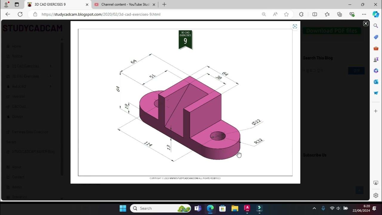
Tutorial Autocad 3D II Studycadcam Exercise 9
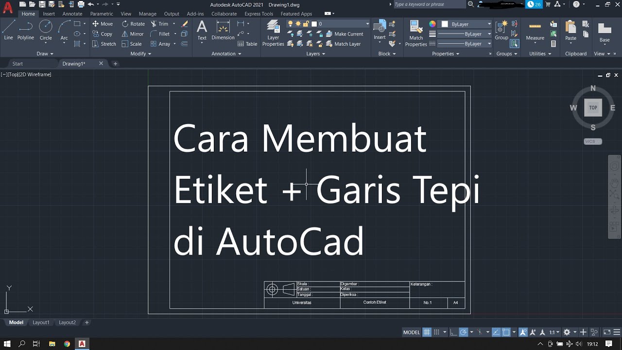
Cara Membuat Garis Tepi dan Etiket Gambar Teknik Kertas A4 di Autodesk AutoCad
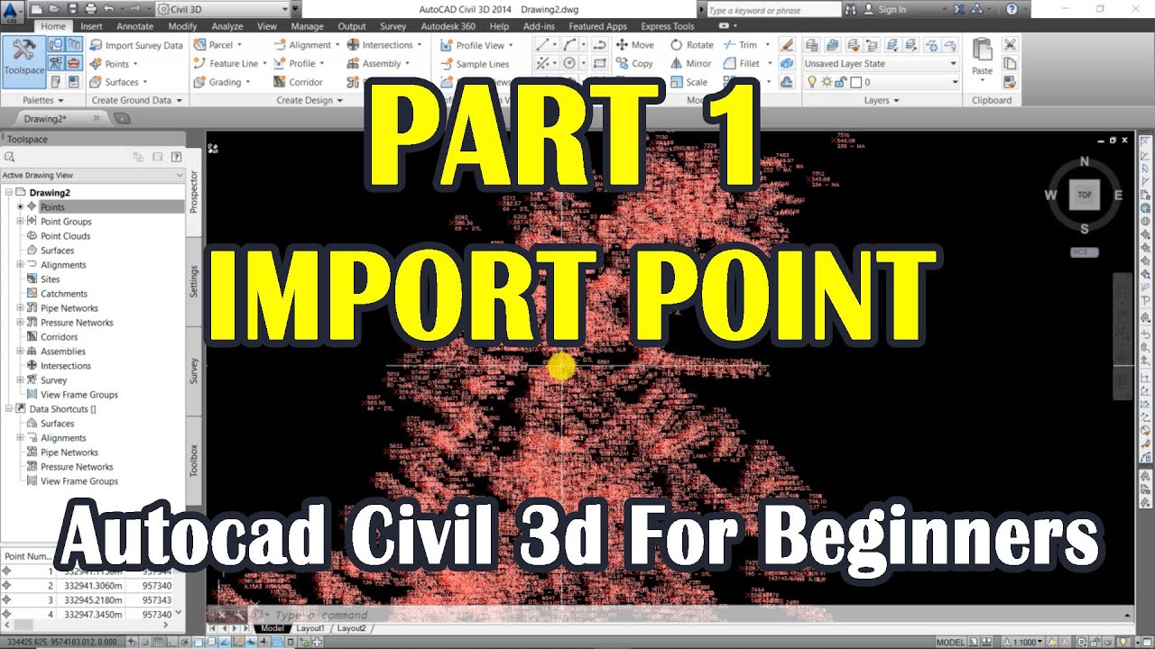
Autocad Civil 3d For Beginners | Import Point | Part 1
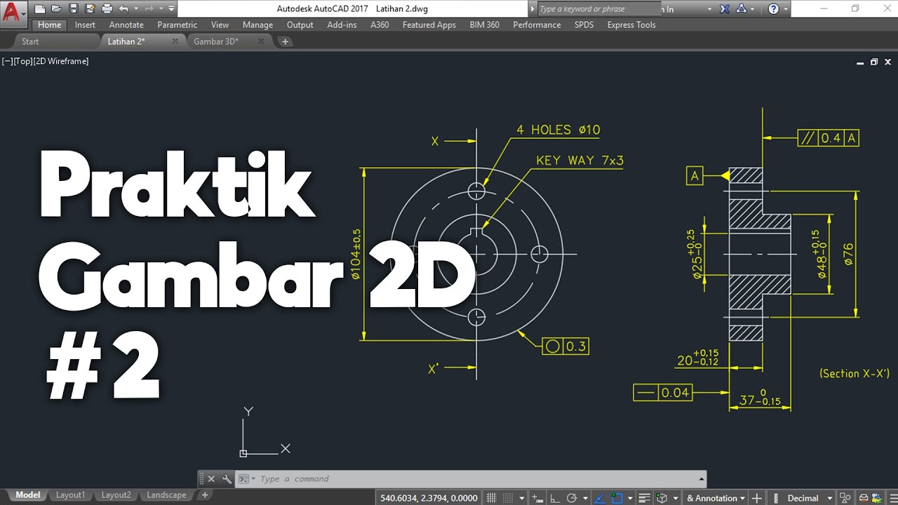
Membuat Gambar Flange 2D dengan Toleransi Geometrik di AutoCAD

cara membuat lebel makanan menggunakan aplikasi pixellab
How to draw PVC Valve in AutoCAD 3D. #autocad_hindi_tutorial #autocaddrawing
5.0 / 5 (0 votes)