AutoCAD Mechanical Tutorial for Beginners - 1
Summary
TLDRThis tutorial introduces AutoCAD Mechanical, guiding users through its user interface and essential tools. It covers template selection, unit setup, basic drawing commands like rectangles and center lines, and introduces the concept of object snaps and dynamic input. The video also demonstrates the creation of mechanical objects, such as center lines, holes, and tapped holes, while explaining layer management and object formatting. Emphasis is placed on using AutoCAD Mechanical’s built-in features to automate tasks, such as layer creation and dimension management, making the design process more efficient. The tutorial concludes with saving, closing, and opening drawings.
Takeaways
- 😀 In AutoCAD Mechanical, using the correct template is essential. For metric drawings, the am_iso.dwt template is used, and for imperial (inches) drawings, the am_ansi.dwt template is used.
- 😀 The AutoCAD Mechanical user interface includes key elements such as the application menu, quick access toolbar, drawing area, and command line.
- 😀 Setting the correct units is vital before starting a drawing. You can set it by typing the 'UN' command, choosing between metric (millimeters) or imperial (inches).
- 😀 The 'amrectang' command is used to create rectangles, and dynamic input should be enabled to see dimensions for length and height as you draw.
- 😀 Center lines can be created using the 'amcentline' command, which allows snapping to key points like midpoints and endpoints for accurate placement.
- 😀 Object snap (OSNAP) can be toggled to help with snapping to specific geometry points like midpoints and endpoints, which is essential for precise drawing.
- 😀 AutoCAD Mechanical automatically manages layers, such as creating layers for center lines (e.g., m7) and assigning line weights according to ISO standards.
- 😀 The 'ampowererase' command is more powerful than the regular 'erase' command in AutoCAD, as it deletes all related objects created by specific commands.
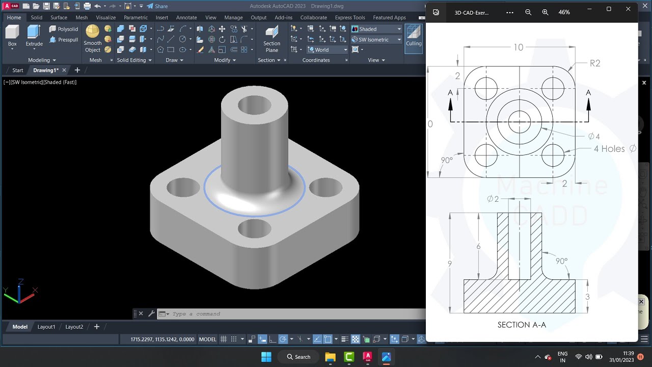
- 😀 For adding holes in a plate, you can use the 'center line cross on plate' command to create holes at defined offsets from the plate's edges or corners.
- 😀 When creating holes, AutoCAD Mechanical offers a range of hole types, including plain holes, tapped holes, and external threads, with customizable standards like metric threads.
- 😀 The 'power dimension' command allows precise dimensioning of objects. It supports automatic snapping to standards-based dimensions and applies layer and color settings automatically.
Q & A
What should you do if you don't have AutoCAD Mechanical, but only have regular AutoCAD?
-If you only have regular AutoCAD, the commands in the AutoCAD Mechanical series will not work. However, you can learn to create mechanical drawings in regular AutoCAD by following the playlist provided in the description.
How do you select a template in AutoCAD Mechanical?
-To select a template in AutoCAD Mechanical, click the arrow to open the template options. Depending on your measurement system (e.g., feet/inches or metric), choose the appropriate template such as am_ansi.dwt for feet/inches or am_iso.dwt for metric.
What is the function of the 'Application Menu' in AutoCAD Mechanical?
-The 'Application Menu' in AutoCAD Mechanical contains basic commands for file handling, such as opening, saving, and printing files.
How do you set the units in AutoCAD Mechanical after selecting a template?
-After selecting a template, use the 'UN' command to set the units. For the am_iso.dwt template, the unit is set to millimeters by default. You can adjust other settings, such as length and angle precision, in this menu.
What is the purpose of 'Dynamic Input' in AutoCAD Mechanical?
-Dynamic Input displays dimensions interactively as you draw. It shows the length and height of shapes like rectangles, making it easier to specify measurements directly while drawing. You can turn it on or off using the dynamic input button.
What is an 'Object Snap' in AutoCAD Mechanical, and how is it used?
-An 'Object Snap' (Osnap) is a feature in AutoCAD Mechanical that helps you snap the cursor to specific points on objects, such as midpoints or endpoints. It can be turned on or off, and you can select which object snaps to use for automatic snapping.
How do you create a center line in AutoCAD Mechanical?
-To create a center line, use the 'amcentline' command. After selecting a point, the center line will automatically be drawn, and you can specify the endpoint or the center point based on object snaps like midpoint or geometric center.
What is the difference between regular 'erase' and 'ampowererase' in AutoCAD Mechanical?
-'ampowererase' is a more powerful erase command in AutoCAD Mechanical. It allows you to erase all objects created by a specific command at once, whereas the regular 'erase' command only deletes the selected object.
How can you create tapped holes in AutoCAD Mechanical?
-To create tapped holes, use the 'Center Line Cross on Plate' command. Select the desired entities, specify the offset for the hole placement, and choose the hole type (e.g., tapped holes) and size, such as M10 for a metric thread.
What are 'Layers' in AutoCAD Mechanical, and how are they managed?
-In AutoCAD Mechanical, layers are automatically created for different types of objects, such as center lines, contours, or holes. The software assigns these objects to appropriate layers based on their type, and you can manage them through the Mechanical Layer Manager.
Outlines

This section is available to paid users only. Please upgrade to access this part.
Upgrade NowMindmap

This section is available to paid users only. Please upgrade to access this part.
Upgrade NowKeywords

This section is available to paid users only. Please upgrade to access this part.
Upgrade NowHighlights

This section is available to paid users only. Please upgrade to access this part.
Upgrade NowTranscripts

This section is available to paid users only. Please upgrade to access this part.
Upgrade Now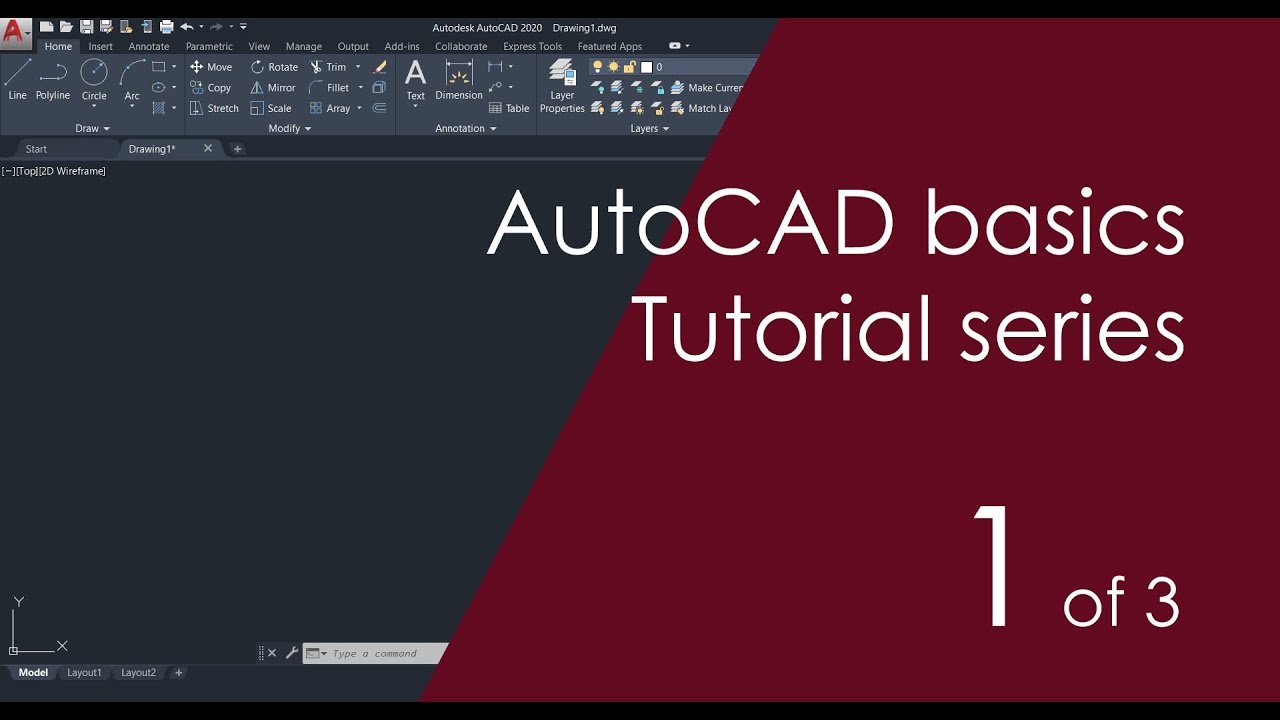


5.0 / 5 (0 votes)