12 Menit Tutorial Desain PCB Eagle 7.6.0
Summary
TLDRThis tutorial provides a step-by-step guide on designing a light-dependent circuit and creating a PCB layout using the PC Beige software version 7.6.0. It covers the necessary components, how to place them on a schematic, and the process of connecting them. The video demonstrates how to convert the schematic into a PCB design, adjusting component placement, adding mounting holes, and creating tracks. Finally, it explains how to save the design as a PDF for easy sharing. Aimed at students in an electronics course, this tutorial offers clear, practical instructions for beginners.
Takeaways
- 😀 Greeting and introduction to the tutorial, including a brief overview of the PCBE 7.6.0 software used for PCB design.
- 😀 The tutorial focuses on creating a light-sensitive PCB circuit using an LDR (Light Dependent Resistor) that activates or deactivates devices based on ambient light conditions.
- 😀 A list of the components required for the project is provided, including resistors, transistors, diodes, relay, and LDR.
- 😀 The process begins by opening PCBE 7.6.0 software, creating a new schematic, and selecting necessary components from the software's library.
- 😀 The user is shown how to place components on the schematic sheet, including resistors, transistors, diodes, and other necessary parts.
- 😀 The tutorial explains how to connect the components using the wire tool, ensuring all parts are linked correctly according to the schematic.
- 😀 A grid view is used to help align components neatly and ensure a clean design layout for the schematic.
- 😀 Once the schematic is complete, the user is instructed to generate the PCB layout and organize components within the designated board boundary.
- 😀 The process of routing the PCB traces is demonstrated, showing how to connect the components on the physical board layout.
- 😀 Final adjustments include adding mounting holes and saving the design in PDF format for easy sharing and printing.
- 😀 The tutorial ends with an invitation to ask questions in a WhatsApp group or via private message for further clarification.
Q & A
What is the purpose of the video tutorial?
-The video tutorial aims to guide students, specifically those studying Electronics at ITTelkom Surabaya, on how to use the PC Beige software to design a PCB (Printed Circuit Board) for a light sensor circuit.
Which version of PC Beige software is used in this tutorial?
-The tutorial uses PC Beige version 7.6.0.
Where can the software used in the tutorial be downloaded from?
-The software can be downloaded from the description column of the video.
What is the light sensor circuit designed to do?
-The light sensor circuit is designed to activate or deactivate electronic devices based on the surrounding light conditions.
What are the components used in the PCB design?
-The components used include a 1kΩ resistor, BC547 transistors, a 50kΩ trimpot, 1N4004 diodes, a 9V relay, an LDR (Light Dependent Resistor), and more.
What components are placed outside the PCB?
-The components placed outside the PCB include a 9V battery, a socket, and a plug.
How do you begin the process of creating the PCB design in the software?
-To begin, open PC Beige 7.6.0, select 'File', then 'New', and finally choose 'Schematic' to start creating the design.
What library is used to insert the components into the PCB design?
-The components are inserted using libraries like 'RCL' for resistors, 'Transistor' for transistors, and 'Relay' for relay components, among others.
How can you make the design process easier when arranging the components?
-To make the design process easier, you can use the 'Grid' option under the 'View' menu to show alignment guides and arrange the components more effectively.
How do you create the PCB tracks once the components are arranged?
-Once the components are arranged, you can create the PCB tracks by using the 'Route' menu to connect the components and define the PCB's electrical paths.
Outlines

This section is available to paid users only. Please upgrade to access this part.
Upgrade NowMindmap

This section is available to paid users only. Please upgrade to access this part.
Upgrade NowKeywords

This section is available to paid users only. Please upgrade to access this part.
Upgrade NowHighlights

This section is available to paid users only. Please upgrade to access this part.
Upgrade NowTranscripts

This section is available to paid users only. Please upgrade to access this part.
Upgrade NowBrowse More Related Video
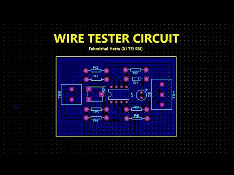
TUTORIAL DESIGN PCB WIRE TESTER USE PROTEUS 8.12 (AUTO PLACER & AUTO ROUTER)
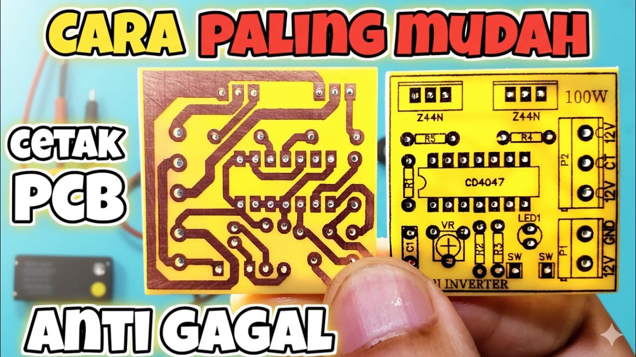
CARA CETAK PCB MANUAL Paling mudah anti gagal

Best Science Project | Smart Street Project | Inspire Award Project | Smart City Project

Cara buat lampu otomatis 220 volt tanpa relay

The Right Way To Plumb A Bathroom In Revit MEP Plumbing Tutorial For Beginners ( Part 1 - Drainage)

NEW Google Sites EASY Student Portfolio
5.0 / 5 (0 votes)