Zynq Part 2: Zynq Vitis Example with PL Fabric GPIO and BRAM
Summary
TLDRIn this video, the creator continues their Zinc design series, focusing on integrating hardware with the CPU side using Vitus. After exporting the hardware from Vivado, the creator demonstrates how to create an application project in Vitus, explaining the importance of selecting the correct version. They walk through using drivers for GPIO and Block RAM peripherals, setting up examples for each, and showcasing a simple application using switches and LEDs. The video highlights how to handle peripheral initialization, driver setup, and memory operations, with the promise of future content covering further design iterations and custom block creation.
Takeaways
- 😀 The video continues from a previous tutorial where the focus is now on writing CPU code and integrating the processor side with the fabric side of a Zynq project.
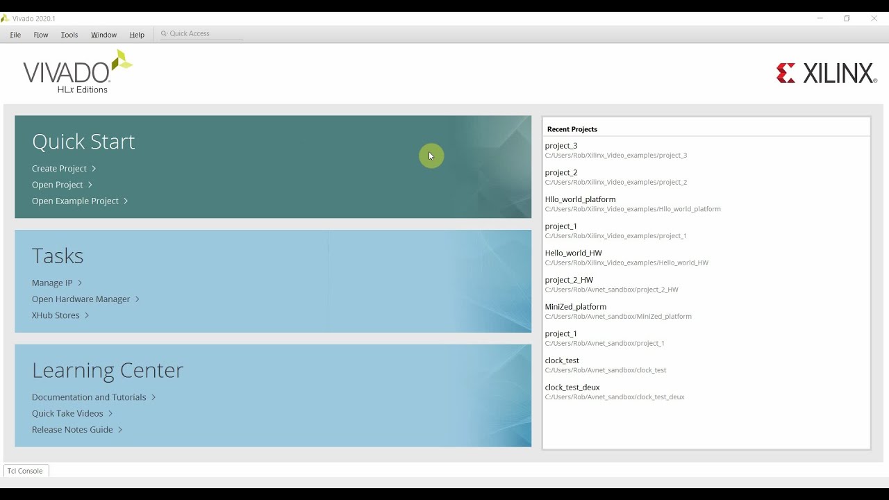
- 😀 The presenter demonstrates how to create a new application project in Vitus IDE by importing an XSA file exported from Vivado.
- 😀 The importance of using Vitus IDE instead of Vitus HLS (High-Level Synthesis) is highlighted, as Vitus provides the option to create an application project.
- 😀 The process of creating the platform for the hardware and linking it to the software application project is discussed in a streamlined manner.
- 😀 The presenter explains the creation of a basic 'Hello World' application to test the system and ensure that everything is set up correctly before moving on to more complex examples.
- 😀 The video emphasizes using BSP (Board Support Package) settings in Vitus to access drivers for peripherals like GPIO and Block RAM that were configured in Vivado.
- 😀 Example code for working with GPIO peripherals is demonstrated, including initializing the GPIO device and writing code to control LEDs based on switches.
- 😀 A simple loop is used to demonstrate how to read the state of switches and control LEDs by linking them in the software, with explanations on handling device drivers and their functions.
- 😀 Block RAM is introduced with an example showing how to write and read data to/from the memory, including the use of the `write_range` and `read_range` functions to manipulate data.
- 😀 The video also discusses useful Vitus features like the ability to find documentation and example code for different peripherals, making it easier for users to understand how to interact with hardware components.
- 😀 The tutorial concludes by previewing potential future topics, including adding custom Verilog/VHDL code to the design, creating custom blocks in Vivado, and managing changes in the design pipeline.
Q & A
What is the primary goal of this video tutorial?
-The primary goal of the video is to demonstrate how to integrate hardware and software on the Zynq platform using Xilinx Vivado and Vitus IDE. The tutorial covers the process of creating a basic hardware design, exporting it, and then writing software to interact with hardware components like GPIO and Block RAM.
What is the difference between Vitus and Vitus HLS?
-Vitus and Vitus HLS are two distinct tools. Vitus IDE is used for creating complete application projects for software running on the CPU, while Vitus HLS (High-Level Synthesis) is primarily used for designing hardware using C, C++, or SystemC. The key distinction is that Vitus IDE supports application-level software development, whereas Vitus HLS focuses on hardware design.
What file is exported from Vivado for use in Vitus?
-The file exported from Vivado for use in Vitus is the XSA (Xilinx Software Architecture) file. This file contains information about the hardware design, including the bitstream and peripheral setups, which are needed for integrating the hardware with the software.
How does Vitus handle the integration of hardware and software components?
-Vitus integrates hardware and software by using the XSA file exported from Vivado. It creates a platform from this file, which allows the software to interface with the hardware. The application project created in Vitus is linked to this platform, enabling the CPU to interact with the programmable logic (PL) and peripherals like GPIO and Block RAM.
What type of project is created in Vitus for the Zynq platform?
-In Vitus, a system project is created for the Zynq platform, which includes a hardware platform (from the XSA file) and an application project. The application project is where the software code (such as 'Hello World') is written to interact with the hardware components on the Zynq device.
What are the key steps in setting up the application project in Vitus?
-The key steps in setting up the application project in Vitus include creating a new platform from the XSA file, setting up the system project with appropriate domain and processor settings, and choosing the application to be run on the processor. Additionally, selecting 'Standalone' as the domain type is crucial for ensuring that the project runs without an operating system.
What peripheral components are demonstrated in the tutorial?
-The tutorial demonstrates the use of GPIO (General Purpose Input/Output) and Block RAM (Random Access Memory) peripherals. These peripherals are included in the hardware fabric and are accessed via drivers in the software project to interact with the hardware components like LEDs and switches.
How does the GPIO example work in the tutorial?
-In the GPIO example, the software reads the state of switches and controls the state of LEDs accordingly. The GPIO driver instance is initialized, and the input/output directions are set. The tutorial demonstrates how to link the switches to the LEDs, such that the LEDs mirror the state of the switches, showcasing the basic GPIO functionality.
What is the purpose of the Block RAM example in the tutorial?
-The Block RAM example is used to demonstrate how to write and read data from Block RAM in the hardware. The tutorial writes incrementing values into the memory and reads them back to verify that the memory functions correctly. This example highlights how software can interact with Block RAM in the FPGA fabric.
What does the presenter suggest as potential next steps in the design process?
-The presenter suggests adding custom Verilog or VHDL code to the design, creating custom blocks in the Vivado block diagram, and iterating on the design by modifying the FPGA fabric. The presenter also plans to demonstrate how to change the fabric and update the design pipeline, as well as how to test and modify the entire system efficiently.
Outlines

This section is available to paid users only. Please upgrade to access this part.
Upgrade NowMindmap

This section is available to paid users only. Please upgrade to access this part.
Upgrade NowKeywords

This section is available to paid users only. Please upgrade to access this part.
Upgrade NowHighlights

This section is available to paid users only. Please upgrade to access this part.
Upgrade NowTranscripts

This section is available to paid users only. Please upgrade to access this part.
Upgrade NowBrowse More Related Video


5.0 / 5 (0 votes)