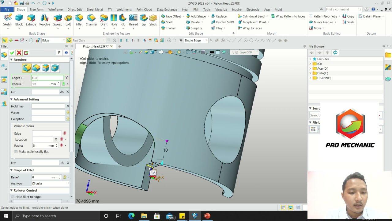
Learn autodesk inventor 3dimensional # 13 mechanical engineering
Summary
TLDRThis tutorial walks users through the basics of creating 3D models using Autodesk Inventor for mechanical engineering. It covers the process of starting with a 2D image, drawing rectangular shapes, applying thickness, and extruding for a 3D effect. Users are shown how to repeat these steps for new parts, adjust dimensions, and add features like holes. The tutorial is beginner-friendly, offering clear instructions and an easy-to-follow approach for creating simple mechanical parts in Inventor. With hands-on examples, this video helps users build foundational skills for working with 3D design tools.
Takeaways
- 😀 Introduction to using Autodesk Inventor for 3D modeling in mechanical engineering.
- 😀 Start by creating a 3D rectangular shape using the 'Rectangle' tool.
- 😀 The first dimension is 20mm, and the second section adds 40mm for a total of 60mm in length.
- 😀 The width of the rectangle is set to 30mm.
- 😀 Use the cut tool to remove parts of the design, setting the thickness to 10mm.
- 😀 Repeat the process to create additional sections with specific measurements (e.g., 40mm length, 20mm width).
- 😀 Adjust the diameter of smaller sections to 10mm to match the design's requirements.
- 😀 Use the tools provided in Autodesk Inventor to make precise adjustments to your design.
- 😀 Finalize the model by checking if it turns yellow, indicating the design is complete.
- 😀 The tutorial emphasizes repeating steps to create different parts of a 3D design for better understanding.
- 😀 Practice and repetition are key to mastering Autodesk Inventor for mechanical design.
Q & A
What is the first step in the tutorial using Autodesk Inventor?
-The first step is opening Autodesk Inventor and starting a new project. The user is then shown a 3D model example, and the tutorial continues with creating the second view of the object.
How do you create a rectangular shape in Autodesk Inventor?
-To create a rectangular shape, you need to select the rectangle tool, then input the desired dimensions for length and width. In this case, the length is 120mm (20 + 40 + 60), and the width is 30mm.
How do you make a cut in the model once the rectangle is drawn?
-After drawing the rectangle, you use the 'Glue' function to make a cut in the model. The cut’s thickness is set to 10mm.
What are the specific dimensions for the second rectangle added to the model?
-The second rectangle has a length of 40mm and a width of 20mm, as measured and inputted into the program.
What diameter should be used for the small parts of the model?
-The diameter for the small parts is set to 10mm in the tutorial.
How do you know when the model is complete in Autodesk Inventor?
-Once the model is complete, the areas should turn yellow. This indicates that all the required elements have been correctly added and are ready for use.
What does the speaker mean by 'measure it here' when creating the shapes?
-When the speaker says 'measure it here', they are referring to checking the dimensions of the shapes and ensuring that the length and width match the required values. This ensures the model is accurate.
What is the purpose of entering the value '10mm' in the thickness field?
-Entering '10mm' in the thickness field defines the thickness of the section of the model that is being created, ensuring consistency in the dimensions.
How are the different levels of the model described in the tutorial?
-The speaker mentions different levels (Level 1, Level 2, Level 3) to help users understand the progression of the model. These levels correspond to the various stages of building the 3D model, making it easier to follow the tutorial.
What is the main takeaway from this Autodesk Inventor tutorial?
-The main takeaway from the tutorial is how to create a basic 3D model using Autodesk Inventor, focusing on adding rectangular shapes, setting dimensions, and making cuts. The tutorial is aimed at beginners looking to grasp fundamental design techniques.
Outlines

This section is available to paid users only. Please upgrade to access this part.
Upgrade NowMindmap

This section is available to paid users only. Please upgrade to access this part.
Upgrade NowKeywords

This section is available to paid users only. Please upgrade to access this part.
Upgrade NowHighlights

This section is available to paid users only. Please upgrade to access this part.
Upgrade NowTranscripts

This section is available to paid users only. Please upgrade to access this part.
Upgrade Now5.0 / 5 (0 votes)


