Smart Home with Google Assistant & Alexa using NodeMCU ESP8266 (Manual + Voice) | IoT Projects 2021
Summary
TLDRIn this Tech StudyCell video, learn to create a home automation system using NodeMCU to control appliances with Google Assistant and Alexa, or manually with switches. The system allows remote control worldwide without needing an Echo Dot or Google Home. The video provides a complete circuit diagram and code, enabling viewers to build this system at home. It also includes a tutorial on using Sinric Pro for device control and configuring both the Alexa and Google Home apps.
Takeaways
- 🌐 This video demonstrates how to create a home automation system using NodeMCU to control appliances with Google Assistant and Alexa app.
- 🔌 The system allows manual control of appliances with switches and real-time monitoring through Google Home and Alexa app.
- 📱 No need for dedicated Alexa or Google Home devices; their Android apps can be used for control.
- 🏠 The video shows how to control appliances even without an internet connection using manual switches.
- 🛠️ The project requires a NodeMCU and a 4-channel relay module, and optionally a custom PCB for a professional finish.
- 🔗 Safety precautions are emphasized when connecting appliances to the relay module.
- 💻 The video provides a complete circuit diagram and code for the project, available on the iotcircuithub.com website.
- 🔑 A Sinric Pro account is necessary for integration with Google Assistant and Alexa, with detailed steps shown for setup.
- 🔑 The video explains how to configure devices in the Sinric Pro dashboard and link them to the Google Home and Alexa apps.
- 🔌 The code provided includes instructions for setting up Wi-Fi credentials, APP KEY, APP SECRET, and device IDs.
- 🔄 The video highlights the need to manage switches correctly during the NodeMCU booting process to avoid issues.
Q & A
What is the main purpose of the video?
-The main purpose of the video is to demonstrate how to create a home automation system using NodeMCU that can control appliances with Google Assistant and Alexa app, as well as manually with switches.
What are the key features of the home automation system presented in the video?
-The system allows for remote control of appliances using Google Assistant and Alexa, manual control with switches, real-time status monitoring in the Google Home and Alexa app, and operation even without an internet connection.
What components are required to build the home automation system?
-The system requires a NodeMCU, a 4-channel relay module, and optionally, existing switch boards or push buttons.
Is it necessary to have a physical Google Home or Alexa device for this project?
-No, a physical Google Home or Alexa device is not necessary. The project can be controlled using their respective Android apps.
How does the system work without an internet connection?
-Without an internet connection, the system can still be controlled manually using the switches, but there will be a delay in the operation of the appliances.
What is the role of the relay module in this project?
-The relay module is used to control the appliances by switching the electrical circuit on and off based on the commands received from Google Assistant, Alexa, or manual switches.
Why is it recommended to use a PCB for the project?
-Using a PCB gives the project a professional look and helps in organizing the numerous connections in a neat and efficient manner.
How can one order a custom PCB for this project?
-One can order a custom PCB from JLCPCB by uploading a Gerber file, selecting parameters like quantity and PCB masking color, and then placing the order.
What are the required libraries for programming the NodeMCU?
-The required libraries include SinricPro, ArduinoJson, and WebSockets.
How does one configure the Sinric account for the project?
-One needs to sign up on Sinric Pro, create rooms and devices, and then use the APP KEY and APP SECRET along with the device IDs in the NodeMCU code.
How are the devices discovered and controlled in the Alexa and Google Home apps?
-After enabling Sinric Pro in the Alexa app and logging in with Sinric credentials, devices can be discovered and controlled. Similarly, in the Google Home app, after setting up a home and linking the Sinric account, devices can be controlled.
What is the limitation when using the free version of Sinric Pro?
-The free version of Sinric Pro allows control of a maximum of 3 devices with Google Home and Alexa app.
Outlines

This section is available to paid users only. Please upgrade to access this part.
Upgrade NowMindmap

This section is available to paid users only. Please upgrade to access this part.
Upgrade NowKeywords

This section is available to paid users only. Please upgrade to access this part.
Upgrade NowHighlights

This section is available to paid users only. Please upgrade to access this part.
Upgrade NowTranscripts

This section is available to paid users only. Please upgrade to access this part.
Upgrade NowBrowse More Related Video
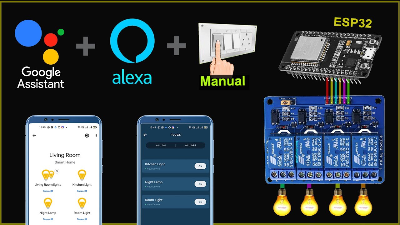
ESP32 Home automation with Google Assistant Alexa & Manual Switches - Internet of Things 2021
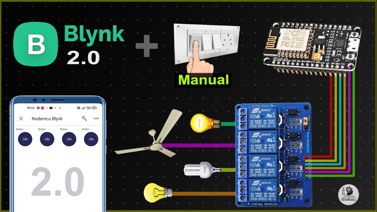
Home Automation using NodeMCU ESP8266 and Blynk 2.0 with real-time feedback | IoT Projects 2021

AIFA Technology-Smart Connection: Traditional Appliances Evolve|Taiwan Excellence

Interruptor Dimerizavel AGL
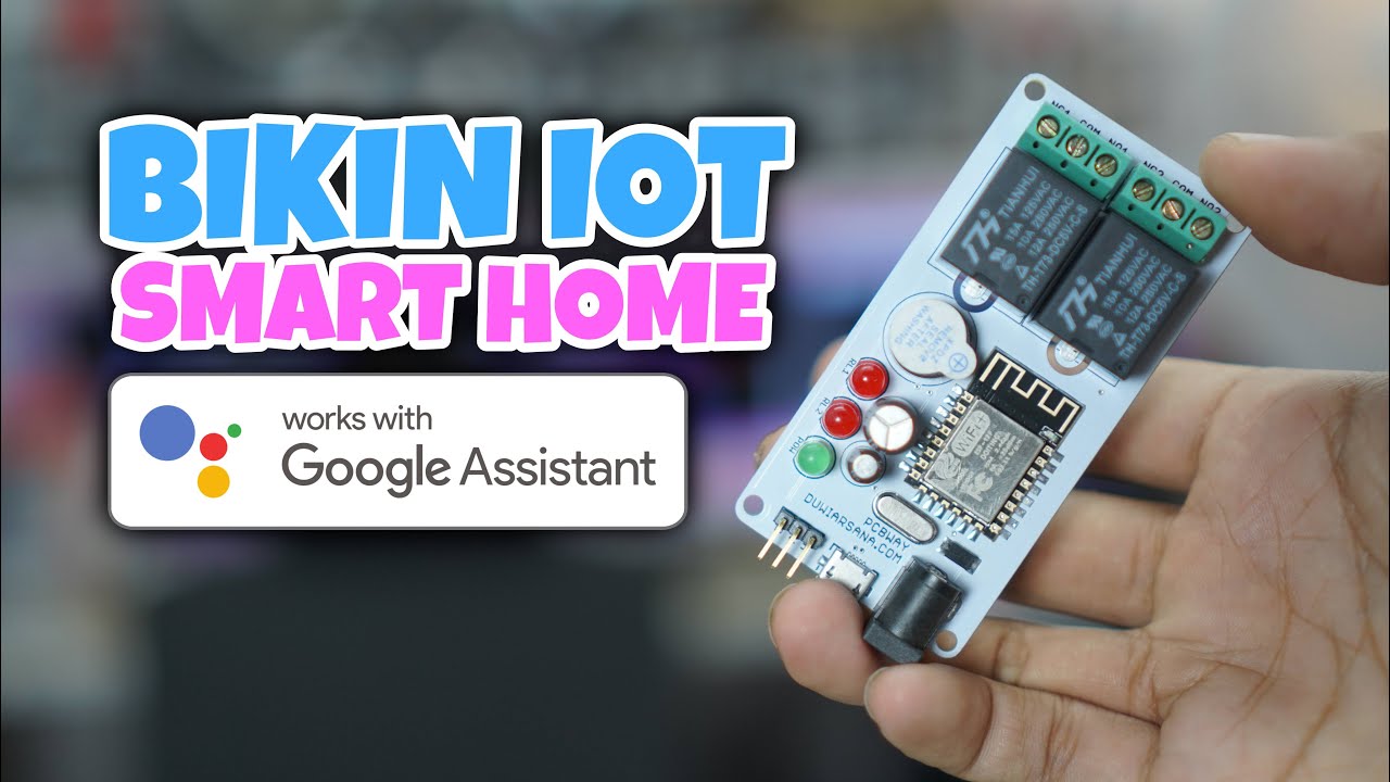
BIKIN IOT SMART HOME GOOGLE ASSISTANT - PCBWAY.COM
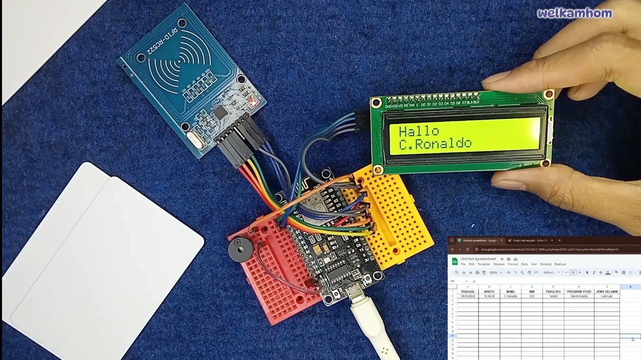
Sistem Absensi Online Menggunakan kartu RFID
5.0 / 5 (0 votes)