PN Junction Diode (No Applied Bias)
Summary
TLDRThis lecture introduces the concept of semiconductor diodes, focusing on the PN junction and its properties. It covers key topics like the formation of a PN junction, volt-ampere characteristics, and the difference between a PN junction and a PN junction diode. The lecture explains biasing (no bias, forward bias, and reverse bias) and details important phenomena such as diffusion current, depletion layer, and barrier potential. The discussion also touches on minority and majority charge carriers, drift current, and the balance between diffusion and drift currents in a steady-state PN junction diode.
Takeaways
- 🔌 PN junction diode is a two-terminal device formed by combining p-type and n-type semiconductors.
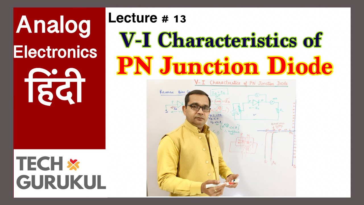
- 📈 The volt-ampere (VI) characteristics of a PN junction diode are critical for understanding its behavior.
- 🔋 Bias refers to applying external voltage across the terminals, with no bias, forward bias, and reverse bias as key conditions.
- ⚡ The diffusion process involves the movement of majority charge carriers from areas of high to low concentration, creating diffusion current.
- 🛡️ The depletion layer is formed due to the recombination of holes and electrons, leaving behind immobile ions that act as a potential barrier.
- 🔄 The barrier potential or built-in potential prevents further movement of free charge carriers, stabilizing the depletion layer's width.
- 🌡️ Minority charge carriers (electrons in p-type, holes in n-type) are influenced by the electric field, creating drift current.
- 🔗 Under steady-state conditions, the diffusion current (from majority carriers) equals the drift current (from minority carriers), resulting in zero net current in an open-circuited diode.
- 🧪 The behavior of the PN junction diode forms the foundation for understanding more complex devices like the bipolar junction transistor (BJT).
- 📏 Future discussions will focus on calculating the barrier potential and the width of the depletion region in a PN junction diode.
Q & A
What is a PN Junction diode?
-A PN Junction diode is a two-terminal device made by combining P-type and N-type semiconductors. It allows current to flow in one direction and has three possible biasing conditions: no bias, forward bias, and reverse bias.
What is the difference between a PN Junction and a PN Junction diode?
-A PN Junction refers to the boundary between a P-type and N-type semiconductor, while a PN Junction diode is the device formed by attaching metal contacts to the terminals of the PN Junction, making it a functional electronic component.
What does 'biasing' mean in the context of a PN Junction diode?
-Biasing refers to the application of external voltage across the two terminals of a PN Junction diode. There are three types of biasing: no bias (no external voltage), forward bias (positive voltage on P-side), and reverse bias (negative voltage on P-side).
What happens in a PN Junction diode under no bias condition?
-In the no bias condition, no external voltage is applied, and the PN Junction is in equilibrium. The diffusion and drift currents are equal and opposite, leading to no net current.
What is diffusion current in a PN Junction diode?
-Diffusion current is caused by the movement of majority charge carriers (holes in P-type and electrons in N-type) from regions of high concentration to low concentration. It occurs due to the concentration gradient across the junction.
What is drift current in a PN Junction diode?
-Drift current is caused by the movement of minority charge carriers (electrons in P-type and holes in N-type) due to the electric field across the depletion region. It is in the opposite direction to the diffusion current.
What is the depletion region in a PN Junction diode?
-The depletion region is the area around the PN Junction where mobile charge carriers (electrons and holes) have recombined, leaving behind immobile positive and negative ions. This region is depleted of free charge carriers and has an electric field across it.
Why is the depletion region also called the space charge region?
-The depletion region is also called the space charge region because it contains immobile ions that create an electric field across the junction, resulting in a region of charged particles without mobile carriers.
What is the barrier potential in a PN Junction diode?
-The barrier potential, also known as the built-in potential, is the electric potential difference across the depletion region that acts as a barrier, preventing the further movement of majority charge carriers.
What happens to the diffusion and drift currents under steady-state conditions?
-Under steady-state conditions, the diffusion current (due to majority charge carriers) and drift current (due to minority charge carriers) are equal and opposite, resulting in no net current flow through an open-circuited PN Junction diode.
Outlines

This section is available to paid users only. Please upgrade to access this part.
Upgrade NowMindmap

This section is available to paid users only. Please upgrade to access this part.
Upgrade NowKeywords

This section is available to paid users only. Please upgrade to access this part.
Upgrade NowHighlights

This section is available to paid users only. Please upgrade to access this part.
Upgrade NowTranscripts

This section is available to paid users only. Please upgrade to access this part.
Upgrade NowBrowse More Related Video
V-I Characteristics of PN Junction Diode in Hindi | TECH GURUKUL By Dinesh Arya

Lab 4 and 5: PN junctions and Solar Cells

Schottky Diode (Construction & Working) Special Purpose Diodes (Basics Electronics)
Types of Diodes - The Learning Circuit

Semiconductor PN Junctions, The Depletion Region and Diode Characteristics
U1_L2_P-N Junction Diode | Electronics Engineering (BEC101/201)| Hindi
5.0 / 5 (0 votes)