What is Hall Effect and How Hall Effect Sensors Work

How To Mechatronics
30 Dec 201503:50

Summary

TLDRIn this educational video from howtomechatronics.com, Dan Luksky explains the Hall effect and its application in sensors. The Hall effect, discovered by Edwin Hall in 1879, is a phenomenon where a voltage is generated across a conductor when a magnetic field is applied perpendicular to the current flow. Hall effect sensors, which are prevalent in modern technology, are used in various applications such as wheel speed sensors in vehicles, MEMS compasses, and proximity sensors. The video delves into the working principles of these sensors, highlighting the differences between analog and digital output sensors, and their specific uses in measuring magnetic fields and detecting positions in mechanical systems.

Takeaways

  • 🧲 The Hall effect is a method for measuring magnetic fields discovered by Edwin Hall in 1879.
  • πŸš— Hall effect sensors are widely used in vehicles for wheel speed sensing, and as position sensors for crankshafts or camshafts.
  • πŸ”§ They are also utilized as switches, MEMS compasses, and proximity sensors in various applications.
  • πŸ”¬ The experiment in the video demonstrates how a magnetic field disturbs the flow of charge carriers in a conductive plate, resulting in a measurable voltage.
  • πŸ“Š Hall effect sensors typically provide a small voltage output, requiring built-in high gain amplifiers.
  • πŸ“‘ There are two types of Hall effect sensors: analog, which offers a continuous output, and digital, which provides binary on/off outputs.
  • πŸ”Œ The analog sensor consists of a voltage regulator, Hall element, and amplifier, suitable for measuring proximity.
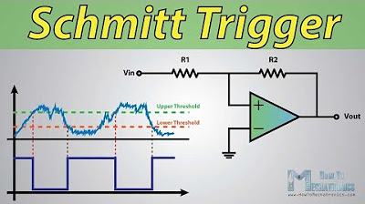
  • πŸ› οΈ Digital output sensors include a Schmitt trigger for hysteresis, useful in applications like limit switches in 3D printers and CNC machines.
  • πŸ”„ Hall effect switches are used for detection and positioning in industrial automation systems.
  • βš™οΈ For measuring wheel speed or engine component positions, sensors use a Hall element and a permanent magnet near a toothed disk on a rotating shaft.

Q & A

  • What is the Hall effect?

    -The Hall effect is a phenomenon where a measurable voltage is generated across a thin conductive plate when a magnetic field is applied perpendicular to the current flow. This effect was discovered by Edwin Hall in 1879.

  • How do Hall effect sensors measure magnetic fields?

    -Hall effect sensors measure magnetic fields by detecting the deflection of charge carriers within a conductive material due to the Lorentz force when a magnetic field is present. This deflection creates a voltage difference across the material, which is proportional to the strength of the magnetic field.

  • What are some contemporary applications of Hall effect sensors?

    -Hall effect sensors are used in various applications such as wheel speed sensors in vehicles, position sensors for crankshaft or camshaft, switches, MEMS compasses, proximity sensors, and in industrial automation systems for detection and positioning.

  • How do Hall effect sensors work in vehicles?

    -In vehicles, Hall effect sensors are used as wheel speed sensors, crankshaft or camshaft position sensors. They provide accurate measurements of speed and position by detecting changes in the magnetic field as a toothed wheel or disk rotates.

  • What is the difference between analog and digital Hall effect sensors?

    -Analog Hall effect sensors provide a continuous output proportional to the magnetic field strength, suitable for measuring proximity. Digital Hall effect sensors have two output states (on or off), often used as switches, with an additional Schmitt trigger for hysteresis and threshold levels.

  • Why do Hall effect magnetic sensors typically require a built-in amplifier?

    -Hall effect magnetic sensors typically provide very small voltages, only a few microvolts per gauss, which are not sufficient for most applications. Therefore, they are usually manufactured with built-in high gain amplifiers to boost the signal to a usable level.

  • What is a Schmitt trigger and how does it relate to Hall effect sensors?

    -A Schmitt trigger is an electronic circuit that provides hysteresis, allowing for two different threshold levels. In Hall effect sensors, it is used to ensure a clean switching between the on and off states, making it suitable for applications like switches and limit sensors.

  • How are Hall effect sensors used for measuring wheel speed or RPM?

    -Hall effect sensors measure wheel speed or RPM by detecting the passing of teeth on a toothed disk attached to the rotating shaft. Each tooth passing near the sensor changes the magnetic field, causing the sensor output to switch states, generating a square wave signal that can be counted to calculate RPM.

  • What is the role of the tooth disk in Hall effect sensor applications?

    -The tooth disk in Hall effect sensor applications is attached to the rotating shaft and has a small gap with the sensor. As the teeth pass by the sensor, they alter the magnetic field, causing the sensor to output a high or low signal, which can be used to determine position or speed.

  • Can you provide an example of a contemporary application of Hall effect sensors in industrial automation?

    -In industrial automation, Hall effect sensors are used for detection and positioning, such as in 3D printers and CNC machines, where they act as limit switches or for precise control of mechanical movements.

Outlines

00:00

🧲 Introduction to Hall Effect and Sensors

In this video, Dan Luksky from howtomechatronics.com introduces the concept of the Hall effect, a phenomenon used to measure magnetic fields. Hall effect sensors are prevalent in modern technology, with applications in vehicles for wheel speed and position sensing, as well as in switches, MEMS compasses, and proximity sensors. The video aims to explain the working principle of these sensors by first demonstrating the Hall effect using a conductive plate experiment. When a current flows through the plate and a magnetic field is introduced, the charge carriers are deflected due to the Lorentz force, resulting in a measurable voltage difference across the plate. This discovery by Edwin Hall in 1879 is the foundation of Hall effect sensors. The video also mentions that these sensors typically provide a small voltage output, necessitating built-in amplifiers. Two types of Hall effect sensors are discussed: analog, which offers a continuous linear output, and digital, which provides binary output states. The analog type is suitable for proximity sensing, while the digital type, often incorporating a Schmitt trigger for hysteresis, is used for applications like limit switches in 3D printers and CNC machines, or for detecting and positioning in industrial automation.

Mindmap

Keywords

πŸ’‘Hall Effect

The Hall Effect is the phenomenon of generating a measurable voltage across a conductive material when a magnetic field is applied perpendicular to the current flow. This effect, discovered by Edwin Hall in 1879, is the foundational principle behind Hall Effect sensors, which measure magnetic fields and have various applications, such as in vehicles and industrial equipment.

πŸ’‘Hall Effect Sensor

A Hall Effect Sensor is a device that detects the presence and strength of a magnetic field using the Hall Effect. These sensors are widely used in modern technology, including in vehicles as wheel speed sensors and in industrial automation systems. The video explains how these sensors work and highlights their use in measuring proximity, speed, and position.

πŸ’‘Magnetic Field

A magnetic field is an invisible field that exerts a force on charged particles, such as electrons, causing them to move. In the context of the Hall Effect, a magnetic field disrupts the flow of current in a conductor, leading to a voltage that can be measured. This principle is utilized by Hall Effect sensors to detect changes in magnetic environments.

πŸ’‘Lorentz Force

The Lorentz Force is the force experienced by charged particles moving through a magnetic field. It causes electrons to deflect to one side of a conductive plate, leading to the creation of the Hall voltage. This force is key to the functioning of Hall Effect sensors, which rely on the deflection of charge carriers to detect magnetic fields.

πŸ’‘Analog Output

Analog Output refers to the continuous, proportional signal generated by some Hall Effect sensors, reflecting the strength of the magnetic field. These sensors provide a variable output that can measure changes in proximity, making them ideal for applications where precise, real-time data is required, such as in speed detection.

πŸ’‘Digital Output

Digital Output is a type of signal generated by Hall Effect sensors that provides discrete on/off states. This output is achieved through the use of a Schmitt Trigger, which creates a clear high or low signal, making it suitable for applications like limit switches in 3D printers and CNC machines.

πŸ’‘Schmitt Trigger

A Schmitt Trigger is an electronic component used in digital Hall Effect sensors to create a hysteresis effect with two different threshold levels. This allows the sensor to output distinct on/off signals, enhancing the stability and accuracy of the sensor's response. The Schmitt Trigger's role is crucial in applications that require precise switching, such as detecting rotational positions.

πŸ’‘Proximity Sensor

A Proximity Sensor detects the presence of nearby objects without physical contact, often using magnetic fields in the case of Hall Effect sensors. The analog output of these sensors allows them to continuously measure distances, making them useful in various contexts, including automotive and industrial applications.

πŸ’‘Crankshaft and Camshaft Position Sensors

Crankshaft and Camshaft Position Sensors are specific applications of Hall Effect sensors used in automotive engines. They detect the position and speed of these engine components, which is critical for the engine's timing and performance. The video explains how these sensors interact with magnetic fields to provide accurate readings for engine management systems.

πŸ’‘Square Wave Signal

A Square Wave Signal is a digital signal with two distinct states, high and low, used by Hall Effect sensors to represent on/off states. This type of signal is commonly used in applications that require precise timing and measurement, such as calculating the RPM of a rotating shaft in engines or other mechanical systems.

Highlights

Hall effect is a common method for measuring magnetic fields.

Hall effect sensors have many contemporary applications.

Hall effect sensors are used in vehicles for wheel speed and position sensing.

They are also used as switches, MEMS compasses, and proximity sensors.

The Hall effect is demonstrated by a conductive plate with a current flowing through it.

A magnetic field disturbs the flow of charge carriers due to the Lorentz force.

Deflection of charge carriers results in a measurable voltage across the plate.

The Hall effect was discovered by Edwin Hall in 1879.

Hall effect sensors typically provide a small voltage, requiring built-in amplifiers.

There are two types of Hall effect sensors: analog and digital output.

Analog sensors provide a continuous linear output proportional to the magnetic field strength.

Digital output sensors provide binary states, often with a Schmitt trigger for hysteresis.

Hall effect switches are used as limit switches in 3D printers and CNC machines.

They are also used for detection and positioning in industrial automation systems.

Hall effect sensors measure wheel speed or RPM using a toothed disk and a permanent magnet.

The output of these sensors is a square wave signal, useful for calculating RPM.

For more tutorials, visit howtomechatronics.com.

Transcripts

play00:07

hello dan luksky here from

play00:08

howtomechatronics.com

play00:10

in this video we will learn what is hall

play00:12

effect and how hall effect sensors work

play00:15

the hall effect is the most common

play00:17

method of measuring magnetic field and

play00:20

hall effect sensors are very popular and

play00:23

have many contemporary applications

play00:25

for example they can be found in

play00:27

vehicles as wheel speed sensors as well

play00:30

as crankshaft or camshaft position

play00:32

sensors also they are often used as

play00:35

switches mems compasses proximity

play00:38

sensors and so on now we will go to some

play00:41

of these sensors and see how they work

play00:44

but first let's explain what is the hall

play00:46

effect

play00:47

here's the experiment that explains the

play00:49

whole effect if we have a thin

play00:51

conductive plate as illustrated and we

play00:54

set current to flow through it the

play00:56

charge carriers both flow in a straight

play00:58

line from one to the other side of the

play01:00

plate

play01:01

now if we bring some magnetic field near

play01:03

the plate we would disturb the straight

play01:06

flow of the charge carriers due to a

play01:08

force called lorentz force in such a

play01:10

case the electrons will deflect to one

play01:13

side of the plate and the positive poles

play01:15

to the other side of the plate

play01:17

this means if we put a meter now between

play01:19

these two sides we will get some voltage

play01:22

which can be measured so the effect of

play01:24

getting a measurable voltage as we

play01:27

explained above is called the hall

play01:29

effect after edwin hall who discovered

play01:31

it in 1879.

play01:34

the basic hole element of the hall

play01:36

effect magnetic sensors mostly provides

play01:39

very small voltage of only few micro

play01:42

volts per gauss so therefore these

play01:44

devices are usually manufactured with

play01:47

built-in high gain amplifiers

play01:49

there are two types of hall effect

play01:51

sensors one providing analog and the

play01:54

other digital output the analog sensor

play01:57

is composed of a voltage regulator a

play01:59

whole element and an amplifier

play02:02

from the circuit schematic we can see

play02:03

that the output of the sensor is analog

play02:06

and proportional to the whole element

play02:08

output or the magnetic field strength

play02:11

this type of sensors are suitable and

play02:13

used for measuring proximity because of

play02:16

their continuous linear output on the

play02:18

other hand the digital output sensor

play02:21

provides just two output states either

play02:23

on or off this type of sensors have an

play02:27

additional element as illustrated in the

play02:29

circuit schematic

play02:30

that's the schmitt trigger which

play02:32

provides hysteresis or two different

play02:35

threshold levels so the output is either

play02:38

high or low for more details how the

play02:40

schmitt trigger works you can check my

play02:42

particular tutorial for that an example

play02:45

of this type of sensor is the hall

play02:47

effect switch they are often used as

play02:50

limit speeches for example in 3d

play02:52

printers and cnc machines as well as for

play02:55

detection and positioning in industrial

play02:58

automation systems

play03:00

another contemporary applications of the

play03:02

hall effect sensors are measuring wheel

play03:05

speed or rpm as well as determining

play03:07

position of crankshaft or camshaft in

play03:10

engine systems

play03:12

these sensors are composed of a hole

play03:14

element and a permanent magnet which are

play03:16

placed near a tooth disk attached on the

play03:19

rotating shaft the gap between the

play03:21

sensor and the teeth of the disc is very

play03:24

small so each time a tooth passed near

play03:26

the sensor it changes the surrounding

play03:28

magnetic field which will cause the

play03:30

output of the sensor to go either high

play03:33

or low

play03:34

so the output of the sensor is a square

play03:36

wave signal which can be easily used for

play03:38

calculating the rpm of the rotating

play03:40

shaft

play03:42

thanks for watching and for more

play03:44

tutorials visit my official website

play03:46

howtomechatronics.com

Rate This
β˜…
β˜…
β˜…
β˜…
β˜…

5.0 / 5 (0 votes)

Related Tags
Hall EffectSensorsMagnetic FieldTechnologyHow-toEducationalElectronicsAutomationMemsTutorial