How to Program a Basic PID Loop in ControlLogix

RealPars
18 Feb 201913:11

Summary

TLDRThis tutorial delves into programming a PID loop control using Rockwell Automation's ControlLogix 5000 PLC and the Enhanced PID controller function block (PIDE). It covers the basics of PID control, the significance of Proportional, Integral, and Derivative gains, and their application in process control. The video guides viewers through configuring the PIDE block in Studio 5000, setting up a control loop for a mixing tank temperature maintenance scenario, and introduces auto-tuning features. It concludes with tips on PID tuning, suggesting the Ziegler-Nichols method for beginners, and invites feedback for further training.

Takeaways

  • 🔧 Programming a control loop is essential for controlling variables like temperature, pressure, and flow rate in automation.
  • 🛠️ A PID controller is designed to apply corrective actions to a process to achieve a desired set point using feedback from a sensor.
  • 🎯 The PIDE function block in Rockwell Automation's ControlLogix 5000 PLC offers enhanced capabilities over the standard PID controller.
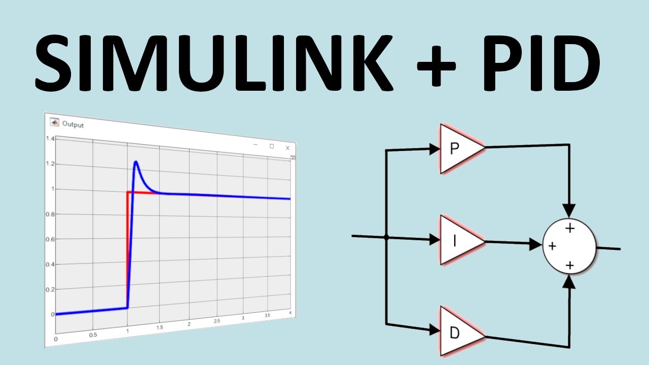
  • 📈 PID stands for Proportional, Integral, and Derivative, which are the three main components of a PID control loop.
  • 🚗 The script uses a car's cruise control as an analogy to explain how PID control works, emphasizing the balance between speed and accuracy.
  • 🔄 The PIDE instruction includes an auto-tune feature, which simplifies the tuning process for the control loop.
  • 💻 The PIDE is programmed using function block diagrams and is not available for ladder logic programming.
  • 📊 The PIDE uses the velocity form of the PID algorithm, which is beneficial for adaptive gains and multi-loop control.
  • 🔧 The PIDE allows switching between 'Program' and 'Operator' modes, providing flexibility in control and full bumpless transfer.
  • 🛠️ The tutorial walks through the process of setting up a PIDE control loop in Studio 5000, including creating tasks, programs, and configuring the PIDE block.

Q & A

  • What is a PID process loop controller used for?

    -A PID process loop controller is used to generate an output that causes some corrective effort to be applied to a process, driving a measurable process variable towards the desired set point value.

  • What are the three components of a PID controller?

    -The three components of a PID controller are the Proportional (P), Integral (I), and Derivative (D) control mechanisms.

  • What does PIDE stand for in the context of Rockwell Automation ControlLogix 5000 PLC?

    -PIDE stands for Enhanced PID controller function block instruction, which is an Allen Bradley Logix5000 Process Automation Controller or 'PAC' family function block that improves on the standard PID.

  • What is the purpose of using a function block in programming a PID loop?

    -Using a function block in programming a PID loop allows for a structured approach with clear input and output connections, making the control logic easier to understand and maintain.

  • How does the PIDE instruction differ from the standard PID instruction?

    -The PIDE instruction offers an enhanced version with features such as a built-in auto tune feature, velocity form of the PID algorithm, the ability to switch between 'Program' and 'Operator' modes, and more fault handling selections.

  • What is the significance of the 'P', 'I', and 'D' in PID control?

    -In PID control, 'P' stands for Proportional gain, 'I' for Integral time, and 'D' for Derivative gain, which together provide a method for a controller to adjust the process to achieve a desired set point.

  • Can you explain the concept of 'Proportional' control in PID?

    -Proportional control in PID refers to the direct relationship between the controller's output and the current error, meaning the greater the deviation from the set point, the stronger the corrective action.

  • What is the role of 'Integral' control in a PID loop?

    -Integral control in a PID loop accumulates the error over time to eliminate any persistent偏差 and ensure the process variable reaches the set point accurately, even if there are systematic errors.

  • How does 'Derivative' control contribute to a PID loop?

    -Derivative control anticipates changes in the process variable based on its rate of change, helping to manage sudden surges and prevent overshooting the target set point.

  • What is the purpose of tuning a PID controller?

    -Tuning a PID controller involves adjusting the P, I, and D parameters to achieve the desired balance between responsiveness and stability in the control loop, ensuring optimal performance.

  • Why is it important to set limits on the control variable in a PID loop?

    -Setting limits on the control variable in a PID loop is important to prevent the actuator from exceeding its operational range and to ensure the process remains safe and within acceptable parameters.

Outlines

00:00

🔧 Introduction to PID Control and PIDE in PLC Programming

This paragraph introduces the concept of PID control loops in automation programming, which are essential for controlling variables like temperature, pressure, and flow rate. It explains the role of a PID controller in managing a process towards a set point using feedback from a sensor and an actuator. The paragraph also highlights the complexity of configuring and tuning PID loops, particularly with Rockwell Automation's ControlLogix 5000 PLC using the Enhanced PID controller function block instruction (PIDE). The PIDE is noted for its improvements over the standard PID, including its function block programming approach and its suitability for process control applications. The 'P', 'I', and 'D' components of PID are described using the analogy of a car's cruise control, illustrating how they respond to deviations from the set point. The paragraph concludes with an invitation to subscribe for more educational content.

05:03

🛠️ Setting Up PIDE in Studio 5000 for Process Control

The second paragraph delves into the practical setup of the PIDE instruction within Rockwell's Studio 5000 environment. It guides the user through creating a new project, selecting a controller, and naming the program 'PIDE_EXAMPLE'. The process of creating a new task, program, and routine is outlined, emphasizing the importance of setting up a periodic task for the PID loop's sample rate. The paragraph continues with instructions on adding the PIDE function block and configuring it for a mixing tank temperature control scenario. It covers the setup of the control valve, temperature transmitter, and the PIDE block's properties, including general configuration, engineering units scaling, and parameter settings. The PIDE's advanced features like auto-tuning, velocity form algorithm, and fault handling are mentioned, along with the steps to create and configure the necessary input and output references for the control loop.

10:07

🎯 Tuning PIDE and Concluding the Tutorial

The final paragraph focuses on the tuning of the PIDE function block and concludes the tutorial. It discusses the selection of tuning parameters with starting points for 'P', 'I', and 'D' gains, recommending the Ziegler-Nichols tuning rules for further guidance. The paragraph summarizes the video's content, emphasizing the learning outcomes that will aid viewers in their automation projects. It invites feedback and suggestions for future topics, encourages viewers to like the video, and directs them to realpars.com for more PLC programming resources. The paragraph serves as a recap and a call to action for continued learning and engagement with the content.

Mindmap

Keywords

💡Control Loop

A control loop in automation programming refers to a closed feedback system that continuously monitors and adjusts a process variable to maintain it at a desired set point. In the script, the control loop is essential for managing variables such as temperature, pressure, and flow rate. The PID controller is a key component of this loop, as it applies corrective actions to drive the process variable towards the set point.

💡PID Controller

The PID controller is a feedback loop controller that is used to regulate a process by calculating an 'error' value as the difference between a desired setpoint and a measured process variable. The acronym PID stands for Proportional, Integral, and Derivative, which are the three terms used to calculate the controller output. The script discusses the configuration and tuning of a PID controller, emphasizing its role in process control.

💡Feedback Process Variable

A feedback process variable is a measured value that reflects the current state of a system, used by a control system to adjust its actions. In the context of the video, the feedback process variable is the actual temperature, pressure, or flow rate being measured by sensors and used by the PID controller to make adjustments.

💡Actuator

An actuator is a device that is responsible for applying the control action commanded by the controller. In the script, the actuator is used to affect the process, such as by opening or closing a valve to adjust the temperature. It is a crucial component in the control loop, as it translates the controller's output into a physical change in the process.

💡Sensor

A sensor is a device that measures a physical quantity and converts it into a signal which can be read by an instrument or controller. In the video script, a sensor is used to measure the process variable, such as temperature, which is then fed back to the PID controller to compare against the set point.

💡Set Point

The set point is the desired value for a process variable in a control system. It is the target that the PID controller aims to achieve. The script mentions setting a set point for temperature control, where the controller will work to maintain the temperature at this specified value.

💡Proportional Gain

Proportional gain is a parameter in the PID controller that determines how much the control output should change in response to the current error. The 'P' in PID stands for 'Proportional,' and it is described in the script as the main ingredient of any control, adjusting the control variable based on the current deviation from the set point.

💡Integral Time

Integral time, or 'I' in PID, is a parameter that accumulates the past errors over time to create a control action that can eliminate a steady-state error. The script explains integral control as a mechanism that adjusts the control variable to achieve accuracy over time, especially when the process variable is consistently below the set point.

💡Derivative Gain

Derivative gain, or 'D' in PID, is a parameter that predicts the future trend of the process variable based on the rate of change of the error. The script uses the example of a sudden wind gust affecting car speed to illustrate how derivative control can prevent overshooting the set point by reacting to rapid changes.

💡Function Block Diagram

A function block diagram is a graphical representation of a program used in PLC programming, where each block represents a function or operation. The script describes using a function block diagram to program the PIDE instruction, which is a structured way to visualize and organize the control logic.

💡Auto Tune Feature

The auto tune feature is a capability of some PID controllers to automatically adjust the PID parameters to achieve optimal control. The script mentions that the PIDE instruction offers a built-in auto tune feature, which can simplify the process of tuning the controller for different processes.

💡Cascade Mode

Cascade mode in a PID controller is a configuration where the output of one controller is used as the set point of another controller in a series. The script explains that the PIDE instruction can be switched into cascade mode, allowing for more complex control strategies where multiple processes are interdependent.

Highlights

Introduction to programming a control loop for process variables like temperature, pressure, and flow rate.

Explanation of PID process loop controller's role in driving process variables towards a set point.

The importance of actuators and sensors in the feedback process of a PID loop.

Overview of configuring and tuning a PID loop control instruction in PLC programming.

Introduction to Rockwell Automation ControlLogix 5000 PLC and its Enhanced PID controller function block instruction (PIDE).

Advantages of PIDE over standard PID instructions in function block programming.

Discussion on the PIDE's built-in auto tune feature and its benefits.

Explanation of the PIDE's velocity form of the PID algorithm for adaptive gains and multi-loop control.

Details on switching between 'Program' and 'Operator' modes and bumpless transfer in PIDE.

Enhanced fault handling selections available in the PIDE instruction.

Step-by-step guide on creating a new Studio 5000 project for PIDE programming.

Instructions on creating a new routine, task, and program in Studio 5000 for PIDE.

Configuration of the PIDE function block for a mixing tank temperature control example.

Setting up Engineering Units Scaling and control variable limits in the PIDE configuration.

Explanation of the PIDE function's parameters and how to select and configure them.

Connecting Input and Output references to the PIDE block for process control.

Tuning the PIDE block with initial 'P', 'I', and 'D' gain settings and the recommendation to use Ziegler-Nichols tuning rules.

Conclusion of the video with a call to action for additional training and feedback.

Transcripts

play00:01

In automation programming,

play00:03

we are often required to program a control loop

play00:06

for a given process to control temperature, pressure, flow rate etc.

play00:12

This requires a target set point with a controlled feedback process variable.

play00:17

A PID process loop controller

play00:20

is designed to generate an output that causes some corrective effort

play00:24

to be applied to a process

play00:26

so as to drive a measurable process variable

play00:29

towards the desired set point value.

play00:31

The controller uses an actuator to affect the process

play00:35

and a sensor to measure the results.

play00:39

Often automation technicians and programmers

play00:42

are required to become familiar with

play00:44

configuring and tuning a PID loop control instruction

play00:48

and it can be one of most overwhelming

play00:51

when it comes to PLC programming topics.

play00:55

In this lesson,

play00:57

we will discuss how a Rockwell Automation ControlLogix 5000 PLC

play01:02

using the Enhanced PID controller function block instruction (PIDE).

play01:08

The PIDE is an Allen Bradley Logix5000 Process Automation Controller

play01:13

or "PAC" family (ControlLogix and CompactLogix) function block

play01:18

that improves on the standard PID found in all their controllers.

play01:35

before we get started on today's video

play01:38

if you love our videos,

play01:40

be sure to click the like button below.

play01:42

then make sure to click subscribe

play01:44

and the little bell to receive notifications of new RealPars videos.

play01:49

This way you never miss another one!

play01:54

Function block programming uses diagrams with symbols

play01:57

to represent function

play01:59

and input and output connections between functions.

play02:04

While at first, this function block can be quite intimidating,

play02:08

it shares similarities of the standard PID instruction

play02:12

and you’ll only need to turn on parameters required by your control program.

play02:17

In this example,

play02:18

we will basically get you off the ground using the PIDE instruction

play02:23

and the program options essential to get it working.

play02:26

In case you may have forgotten what PID stands for,

play02:30

the “P” stands for “Proportional” gain,

play02:33

“I” for “Integral” time

play02:35

and “D” for “Derivative” gain.

play02:39

PID and PIDE are used for "process control"

play02:43

which includes the automatic control of systems such as temperature,

play02:47

flow rate, pressure, and speed.

play02:52

The cruise control on a car is a good example of this type of control.

play02:57

Basically, you tell the controller how fast you want to go,

play03:00

the Set point and the controller samples the actual speed,

play03:04

the Process Variable,

play03:06

and then the controller calculates an output value, the “Control Variable”,

play03:10

and sends that signal to the gas pedal.

play03:15

And just as a PID functional refresher,

play03:18

and using the car cruise control as an example,

play03:21

the “P” or proportional

play03:24

is described as in the farther you are from the desired speed,

play03:27

the more you press the gas pedal and on the other hand,

play03:31

the closer you are, the less you press on it.

play03:34

This works well but when you get at the desired speed,

play03:37

based on this rule you would let off the gas completely.

play03:41

And the end result is your car slows down

play03:44

and stays a little below the desired speed.

play03:48

Proportional control is the main ingredient of any control

play03:52

but maybe a little inaccurate.

play03:56

For “I “or integral, you wait for a little,

play04:00

and if there is no improvement you push a little more on the pedal.

play04:04

If you are stuck below the desired speed for a long time without progress,

play04:09

you push the gas pedal a little further.

play04:11

If you still do not make it to the desired speed for some time,

play04:15

you again push the pedal a little further down.

play04:19

Once you get to the desired speed you leave the pedal where it is.

play04:25

Integral control gives you accuracy but you have to wait.

play04:31

And for “D” or derivative, you react to sudden changes.

play04:36

Let’s say a strong wind gust pushes your car.

play04:39

Suddenly your speed surges fast upward toward the desired speed.

play04:44

You become startled so you release the gas pedal.

play04:47

As the speed surge ends and the speed stabilizes,

play04:51

you will then return the pedal to where it was.

play04:54

Derivative control manages sudden surges

play04:57

and may prevent overshooting your target speed.

play05:02

If you enjoy function block programming, as I do,

play05:06

you will benefit from using this enhanced version instruction

play05:09

over the standard PID instruction for a few reasons.

play05:14

The PIDE instruction offers a built-in auto tune feature

play05:19

which works reasonably well,

play05:21

the PIDE is programmed using a function block

play05:24

and not available for ladder logic programming,

play05:27

it uses the velocity form of the PID algorithm.

play05:31

This is especially useful for adaptive gains

play05:34

or multi loop and cascade process control.

play05:38

The PIDE instruction can be switched between “Program” and “Operator” modes

play05:44

and provides full bumpless transfer

play05:46

into and out of cascade mode,

play05:49

and this instruction has more fault handling selections.

play05:56

The following programming steps assume the reviewer

play05:59

has Studio 5000 experience.

play06:02

Okay, let’s get started and create a new “Studio 5000” project.

play06:08

Locate the desktop or taskbar icon for Studio 5000 and launch the program.

play06:15

Create a new project,

play06:17

select a new controller type

play06:19

such as the 1756-L71 and give the program a name,

play06:25

in this case, “PIDE_EXAMPLE”.

play06:30

Hit “Next” and in the next window

play06:32

keep everything as it is and then click Finish.

play06:38

For the next step we need to create a new “Routine”

play06:42

by making a new “Task” and a new “Program”.

play06:46

So first I’ll create a new scheduled task by right clicking on the “Tasks”

play06:51

and then clicking on the “New Task”.

play06:54

In the next window I will consider “PIDE_CONTROL”

play06:58

as the name for the task.

play07:02

The period of the task automatically becomes the sample rate of the PID loop.

play07:07

it is best to set it up in its own periodic task.

play07:11

So, I’ll leave these settings without any changes

play07:14

and continue to create a “New Program”

play07:17

by right clicking on the “PIDE_CONTROL” Task.

play07:20

In this menu, I’ll open the “Add” menu and click on the “New Program”.

play07:27

I will name the program as same as the “Task”, which is “PIDE_CONTROL”.

play07:33

Finally, I’ll click OK to close this window.

play07:37

The next step in the process is to create a new “Routine”.

play07:41

To do that I’ll right click on “PIDE_CONTROL” Program,

play07:45

then “Add” and then I’ll select “New Routine”.

play07:50

In this window, I will name the “New Routine” as “PIDE”.

play07:55

Just make sure to select the Type

play07:57

as “Function Block Diagram” and then click OK.

play08:01

As you can see, the “PIDE” icon is added here

play08:06

and I can open it up by double clicking on it.

play08:10

Now that I have opened the “PIDE” program,

play08:13

from the “Process” tab in the library,

play08:15

I will add the PIDE function and add it onto the sheet.

play08:22

Now let’s suppose we have a mixing tank

play08:24

where the temperature is to be maintained at a certain set point.

play08:28

The control valve allows a catalyst to be added to the tank

play08:31

to increase the temperature

play08:33

and the temperature transmitter will send the feedback to the PID.

play08:38

This will represent our process and control loop for programming purposes.

play08:45

Now to be able to configure this block I need to open up the properties.

play08:51

To do that I’ll simply double click on the block.

play08:56

In the “General Configuration” tab,

play08:59

we will use the default configuration.

play09:01

However, we just need to make sure that for the “Timing”

play09:05

it is using “Periodic Mode”,

play09:08

the “Control Action” is set to “E”

play09:11

and for the “Calculate” it is using the “Proportional” parameter set to “E”

play09:18

and the “Derivative Term” is set to “PV”.

play09:22

Next, in the EUs/Limits tab,

play09:24

I will set the “Engineering Units Scaling”

play09:27

for both “CV” and “PV” parameters

play09:30

from 0 to 2500 degrees Fahrenheit,

play09:35

with a set point limit of 500 to 2200 degrees Fahrenheit.

play09:41

The control variable limits will be using the same temperature engineering units.

play09:46

In the “Parameters” tab,

play09:48

there are several parameters which PIDE function utilizes them

play09:52

that you may or may not use them.

play09:55

These parameters can be manually turned off or on here.

play09:59

When selected, the parameter will be exposed to allow program connections.

play10:07

Here there is also a “Description” field for each parameter

play10:10

which gives you more information about them.

play10:14

I’ll select the required parameters and deselect the rest.

play10:19

Next I’ll hit OK to save the configuration.

play10:25

You can see the required parameters I’ve selected in the PIDE block here.

play10:31

After the PIDE function block is configured

play10:35

we can begin to add program control Input and Output reference tags

play10:39

to adjust the PIDE block performance.

play10:43

The main Input references are the Temperature PV

play10:47

or process variable which is a feedback from temperature transmitter,

play10:51

the SPProg or Program Set point which is defined by the operator on the HMI,

play10:57

and the CVEU or “Control Value in Engineering Units” output

play11:02

to control the heat in the tank by opening or closing the control valve.

play11:07

Other inputs added are inputs for the controlling the set point high and low limits,

play11:13

the maximum and minimum Engineering Units

play11:17

and Auto_Manual control

play11:19

to allow for direct manual control of the catalyst control valve.

play11:24

The CV_Manual input reference value

play11:27

will be used for the manual control when Auto_Manual is turned OFF.

play11:32

The PIDE will need to be tuned and we have set the tuning parameters “P” gain to 1,

play11:40

“I” gain to 0.5 and “D” gain to 0 to a recommended starting point.

play11:49

PID tuning can be tricky

play11:51

so I recommend reviewing procedures for this technique.

play11:55

The standard reference for PID tuning seems to be the Ziegler-Nichols tuning rules.

play12:02

This concludes the video ,

play12:04

Programming Basic ControlLogix PID loop using the PIDE block instruction.

play12:10

I hope you have enjoyed learning what will support you in your upcoming project.

play12:15

If you would like to get additional training on a similar subject,

play12:18

please let us know in the comment section.

play12:21

If you enjoyed this video, please press the like button.

play12:25

Please check back with us soon for more automation control topics.

play12:34

Want to learn PLC programming in an easy to understand format

play12:39

and take your career to the next level?

play12:43

Head on over to realpars.com

Rate This

5.0 / 5 (0 votes)

Related Tags
AutomationPID ControlControlLogixPLC ProgrammingProcess ControlTuning TechniquesIndustrial AutomationProgramming TutorialZiegler-NicholsFunction Block