AutoCAD Basic Tutorial for Beginners - Part 2 of 3
Summary
TLDRThis tutorial offers an in-depth guide to mastering basic drawing and modifying tools in AutoCAD. It covers creating lines, polylines, circles, and rectangles with precision, utilizing dynamic input and object snap features. The instructor demonstrates how to manipulate objects using commands like move, copy, rotate, and mirror, and introduces advanced techniques such as filleting and offsetting. The video concludes with a practical example, illustrating how these tools are applied to create a complex 2D drawing, setting the stage for discussions on drawing management and plotting in subsequent lessons.
Takeaways
- 🔧 The script provides an in-depth tutorial on using various drawing and modifying tools in a CAD software.
- ✅ It emphasizes the difference between the 'line' and 'polyline' tools, highlighting how polylines treat a series of connected lines as a single entity.
- 🔲 The 'circle' tool is introduced with options to create circles by specifying radius or diameter, catering to different user preferences.
- 🌀 The 'arc' tool is showcased, allowing users to create arcs by defining three points or using other arc-specific features.
- 📏 The 'rectangle' tool is explained, demonstrating how to create rectangles either by clicking two corners or by specifying dimensions with dynamic input.
- 🔄 The 'pan' tool is mentioned for moving the entire drawing area, and the 'move' tool is introduced for relocating selected objects.
- 🔄 The 'copy' command is highlighted as a way to duplicate objects without altering the original.
- 🔄 The 'rotate' tool is explained, showing how to rotate objects around a specified base point by a given angle.
- 🔄 The 'mirror' tool is demonstrated, allowing users to create symmetrical designs by mirroring objects across a defined line.
- 🔄 The 'fillet' tool is introduced, used for rounding the corners of sharp angles in a drawing by applying a specified radius.
- ✂️ The 'trim' tool is explained, used to remove unwanted parts of intersecting lines or shapes up to the nearest boundary.
- 🔄 The 'offset' tool is described, enabling users to create parallel lines or shapes at a specified distance from the original.
- 📏 The importance of the 'object snap' feature is stressed for precise alignment and selection of points such as endpoints, midpoints, and intersections.
- 🎨 The script concludes with a practical example of creating a complex 2D drawing using the discussed tools, demonstrating their real-world application in CAD.
Q & A
What is the basic difference between the line and polyline tools in CAD?
-The basic difference between the line and polyline tools in CAD is that when you select polyline, the complete set of lines will be selected as it forms a connected curve, whereas with the line tool, only a particular segment will be selected, and all of these are separate.
How can you create a circle with a specific radius in CAD?
-To create a circle with a specific radius in CAD, you can select the circle tool, click at a point, and then type in the radius value followed by pressing Enter.
What is the purpose of the arc tool in CAD?
-The arc tool in CAD is used to create different kinds of arcs. It allows making three-point arcs using first, second, and third points, and there are other features for creating various arc types depending on the workflow and drawing requirements.
How do you make a rectangle with specific dimensions in CAD?
-To make a rectangle with specific dimensions in CAD, use the rectangle tool, click at a point, and then type in the length and width values after pressing the Tab key, followed by pressing Enter.
What is the function of the pan tool in CAD?
-The pan tool in CAD is used to move the entire drawing area. It can be activated by pressing and holding the mouse wheel and then panning around.
How can you move a specific object in CAD without moving the entire drawing?
-To move a specific object in CAD without moving the entire drawing, use the move select tool from the modify panel. Select the object, press Enter, choose a base point, and then move it to the desired location.
What does the copy command do in CAD?
-The copy command in CAD creates copies of the selected object(s). It works similarly to the move command but instead of moving the original object, it duplicates it.
How can you rotate an object in CAD?
-To rotate an object in CAD, use the rotate tool, select the object, press Enter, specify the base point, and then enter the rotation angle to rotate the object by that angle.
What is the mirror tool used for in CAD?
-The mirror tool in CAD is used to create a mirror image of any object. You select the object, press Enter, specify a mirroring line by clicking two points, and the tool creates a mirrored copy of the original object.
How do you use the fillet tool to round the corners of a drawing in CAD?
-To use the fillet tool to round the corners of a drawing in CAD, select the fillet tool, choose the radius option, specify the radius value, and then click on the lines where you want the fillet to be applied.
What is the trim tool used for and how do you use it in CAD?
-The trim tool in CAD is used to remove unwanted parts of intersecting objects. After selecting the trim tool and pressing Enter, click on the part of the drawing that you want to trim, and it will trim up to the next boundary.
How can you create an offset of an object in CAD?
-To create an offset of an object in CAD, use the offset tool, type in the offset distance, select the boundary, and then move it inwards or outwards to create the offset copy.
Why is the object snap feature important in CAD?
-The object snap feature is important in CAD because it allows for precise alignment and selection of specific points on objects, such as endpoints, midpoints, centers, and intersections, which is crucial for accurate drawing.
Outlines

This section is available to paid users only. Please upgrade to access this part.
Upgrade NowMindmap

This section is available to paid users only. Please upgrade to access this part.
Upgrade NowKeywords

This section is available to paid users only. Please upgrade to access this part.
Upgrade NowHighlights

This section is available to paid users only. Please upgrade to access this part.
Upgrade NowTranscripts

This section is available to paid users only. Please upgrade to access this part.
Upgrade NowBrowse More Related Video
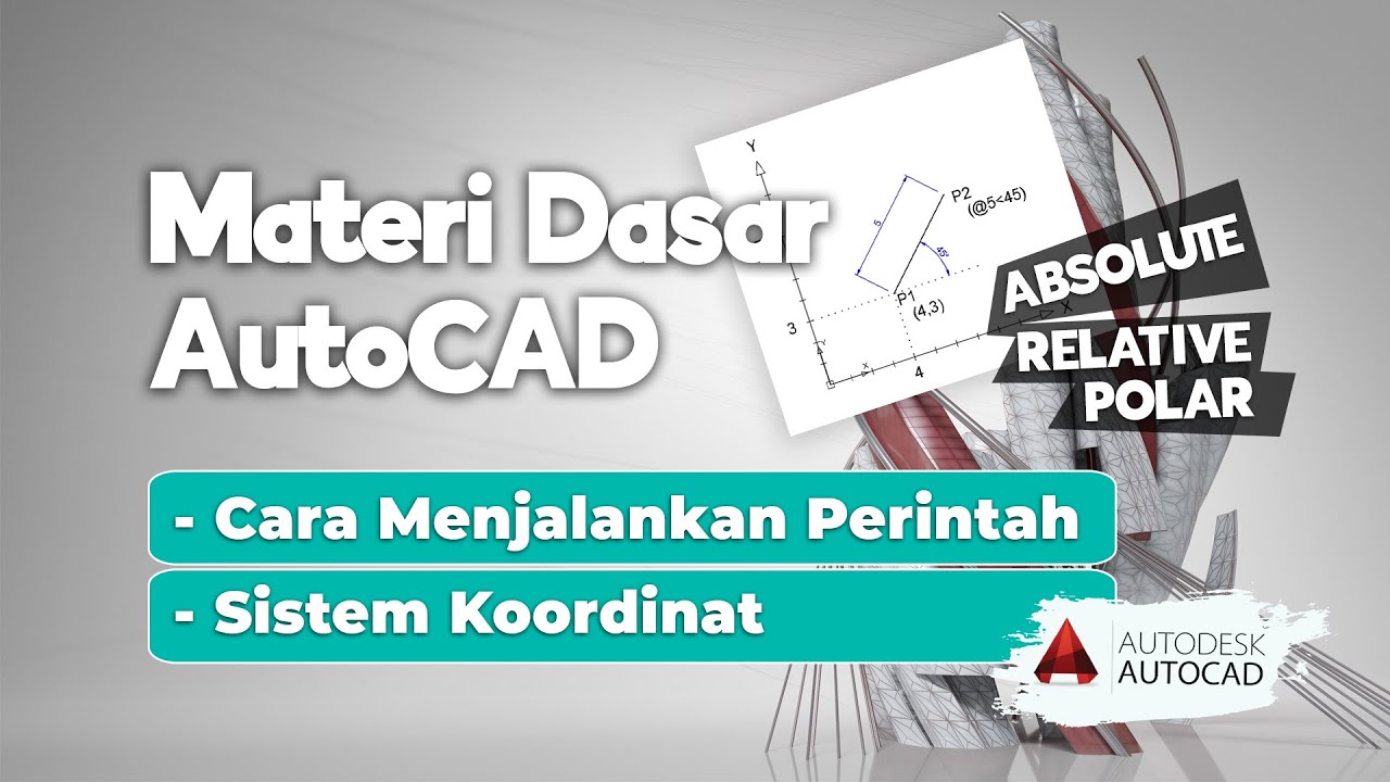
Cara Menjalankan Perintah AutoCAD & Sistem Koordinat AutoCAD | Belajar AutoCAD dari Nol #4
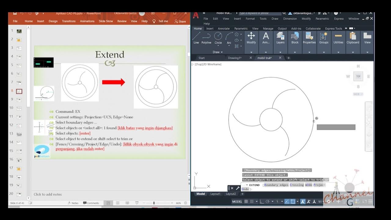
AutoCAD - Merubah Obyek (Offset, extend, fillet, linetype, devide, Point Style)
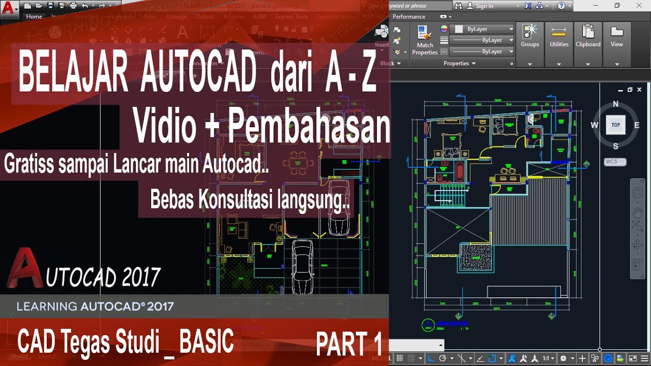
Autocad For Beginer [ Part 1 ] Belajar Autocad Dasar
autocad tutorials for beginners
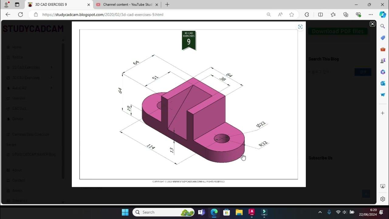
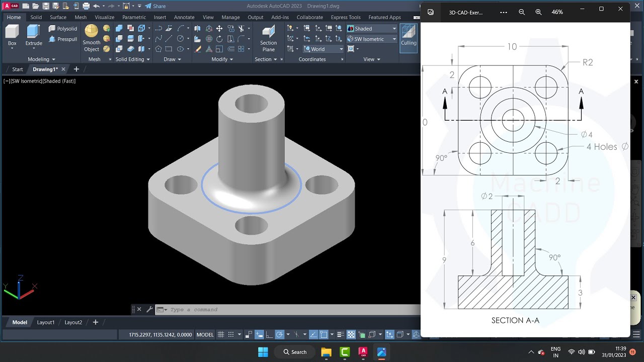
Tutorial Autocad 3D II Studycadcam Exercise 9
AutoCAD 2025 - 15 Minute Tutorial for BEGINNERS!
5.0 / 5 (0 votes)