BELAJAR LADDER PROGRAM PLC DARI NOL | EPISODE 1 | GERBANG LOGIKA AND
Summary
TLDRIn this educational video on PLC programming, the basics of Ladder Logic are explained in detail. The video covers how PLCs use ladder diagrams to synchronize input and output components, enabling efficient control systems. The presenter explains the use of logic gates like AND, OR, and NOT, along with practical examples such as Normally Open (NO) and Normally Closed (NC) push buttons. The video illustrates how pressing specific buttons can trigger outputs like an LED light, offering a foundational understanding of PLC programming concepts.
Takeaways
- 😀 PLCs (Programmable Logic Controllers) require a program to operate control systems effectively.
- 😀 Ladder Logic (also called leader program) synchronizes input and output components to execute control processes.
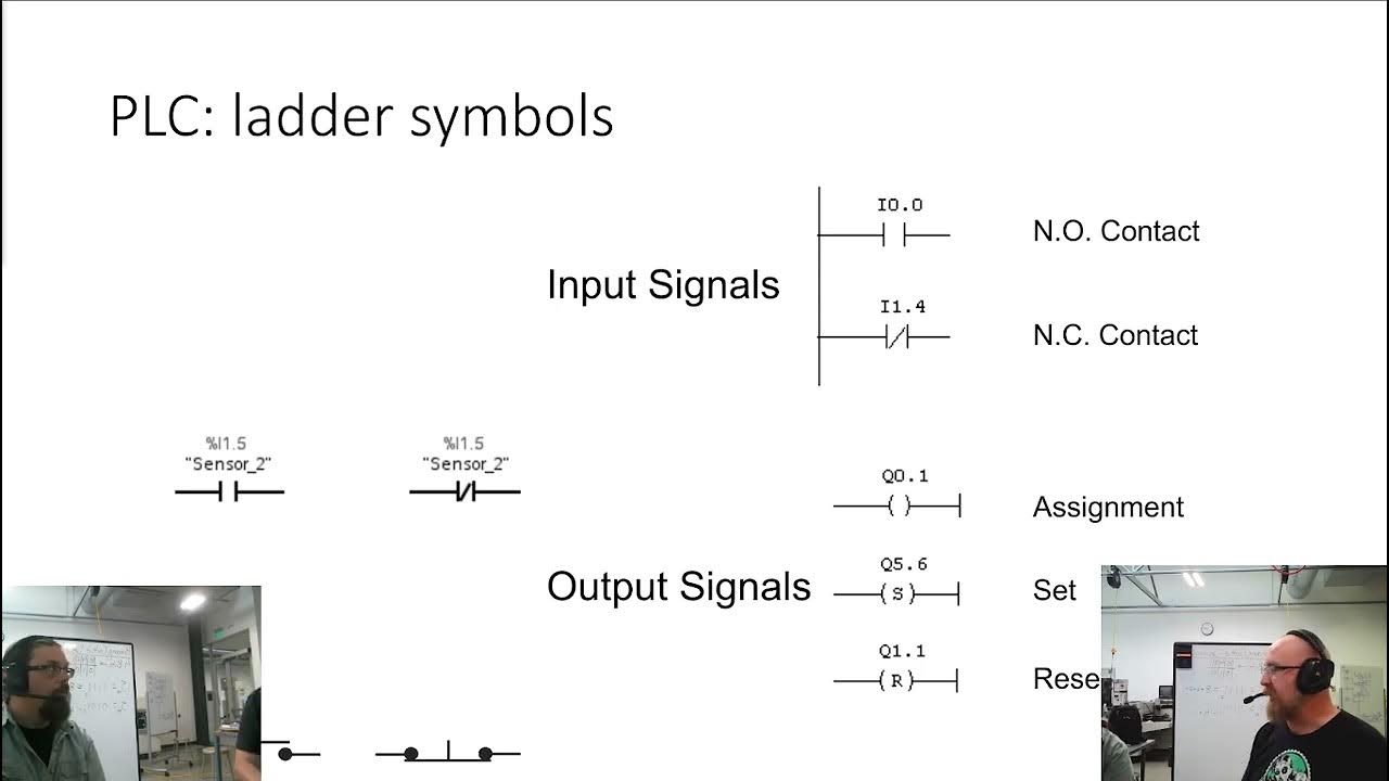
- 😀 In a ladder diagram, inputs are positioned on the left and outputs on the right, resembling electrical circuits.
- 😀 Each horizontal line in a ladder diagram is called a 'rung' and is read from left to right, top to bottom.
- 😀 Logic gates such as AND, OR, and NOT are used to process inputs and control outputs in PLCs.
- 😀 Discrete inputs have only two states: ON or OFF.
- 😀 Normally Open (NU) contacts close when the input is activated, while Normally Closed (NC) contacts open when activated.
- 😀 Example wiring: a NU push button connects positive DC 24V to the PLC input when pressed.
- 😀 Example wiring: a NC push button disconnects positive DC 24V from the PLC input when pressed.
- 😀 A practical example is using two NU push buttons in an AND gate configuration to turn on a red LED when both are pressed simultaneously.
Q & A
What is the main purpose of a leader program in a PLC system?
-The leader program is used to synchronize input and output components in a PLC system, ensuring that the control logic processes inputs correctly to activate the corresponding outputs.
Which programming language is most commonly used in PLC systems?
-Ladder Logic is the most commonly used programming language in PLC systems due to its simplicity and its resemblance to electrical wiring diagrams.
What are the key components of a leader program?
-A leader program consists of input components that are processed into control logic, and output components that are activated based on the logic.
What is the difference between normally open (NO) and normally closed (NC) contacts in PLC input systems?
-Normally open (NO) contacts are open in their default state and close when activated, while normally closed (NC) contacts are closed in their default state and open when activated.
What role do logic gates like AND, OR, and NOT play in a PLC system?
-Logic gates like AND, OR, and NOT are used to compare input conditions and determine the corresponding output states. For example, an AND gate requires all inputs to be active for the output to be triggered.
Can you give an example of how Ladder Logic works in a PLC control system?
-An example is using two push buttons (PB1 and PB2) in an AND operation to control an LED. The LED turns on only when both buttons are pressed simultaneously.
What is the function of a discrete input in a PLC system?
-Discrete inputs, such as push buttons, provide binary signals (ON or OFF) that are used to trigger specific actions or outputs in the system.
How does the state of a normally open (NO) contact change when the push button is pressed?
-When the push button connected to a normally open (NO) contact is pressed, the contact closes, allowing the current to flow and activating the corresponding input in the PLC.
What happens to the input state of a normally closed (NC) contact when the push button is pressed?
-When the push button connected to a normally closed (NC) contact is pressed, the contact opens, interrupting the current flow and deactivating the input in the PLC.
Why is Ladder Logic often preferred for PLC programming?
-Ladder Logic is preferred because it closely resembles electrical circuit diagrams, making it easier for engineers familiar with electrical systems to understand and implement control logic.
Outlines

Этот раздел доступен только подписчикам платных тарифов. Пожалуйста, перейдите на платный тариф для доступа.
Перейти на платный тарифMindmap

Этот раздел доступен только подписчикам платных тарифов. Пожалуйста, перейдите на платный тариф для доступа.
Перейти на платный тарифKeywords

Этот раздел доступен только подписчикам платных тарифов. Пожалуйста, перейдите на платный тариф для доступа.
Перейти на платный тарифHighlights

Этот раздел доступен только подписчикам платных тарифов. Пожалуйста, перейдите на платный тариф для доступа.
Перейти на платный тарифTranscripts

Этот раздел доступен только подписчикам платных тарифов. Пожалуйста, перейдите на платный тариф для доступа.
Перейти на платный тарифПосмотреть больше похожих видео

Example PLC: EATON EASY Intelligent Relay (Full Lecture)
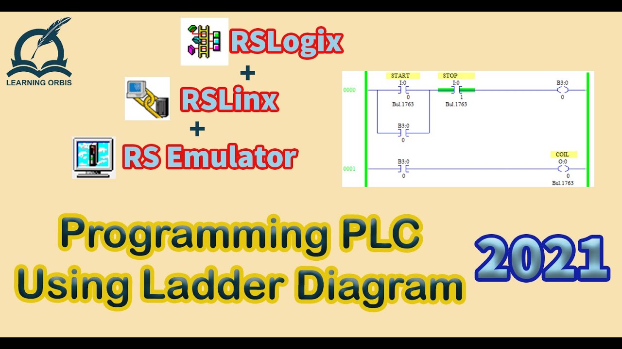
How to Program PLC Using Ladder Diagram | RSLogix

DASAR PEMOGRAMAN PLC - SIMBOL - SIMBOL DASAR PLC
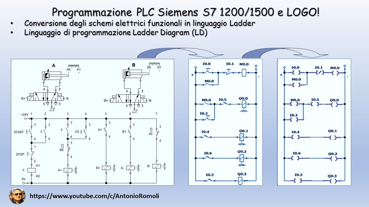
PLC: convertire lo schema elettrico funzionale in linguaggio di programmazione Ladder (Video 1.1)
SysAp 7 1 Ladder Logic

How to Download, Install, Program and simulate WPLSoft Delt PLC Software
5.0 / 5 (0 votes)
