BELAJAR 2 PEMROGRAMAN ARDUINO PEMULA - SERIAL MONITOR, PINMODE, DIGITALWRITE
Summary
TLDRIn this Arduino tutorial, the creator demonstrates how to set up a pin, particularly pin 13, for use as either input or output. The video covers defining variables, configuring pin modes, and writing basic code to control an LED attached to pin 13. Key concepts like serial communication, using the serial monitor, and functions such as `digitalWrite()` and `delay()` are explained. The tutorial also walks through setting up the Arduino IDE, uploading code, and testing the functionality of the LED, making it a beginner-friendly guide for learning the basics of Arduino programming.
Takeaways
- 😀 Define a variable for a pin (e.g., pin 13) to simplify the code and make it more flexible.
- 😀 Pin modes in Arduino can be set as either input or output using the 'pinMode()' function.
- 😀 An input pin receives voltage or signals into the Arduino, while an output pin sends voltage or signals out from the Arduino.
- 😀 In this example, pin 13 is set as an output to control an LED connected to it.
- 😀 The 'digitalWrite()' function is used to control the output state of a pin (HIGH or LOW), turning the LED on or off.
- 😀 Serial communication with the computer is established using 'Serial.begin()' with a baud rate (e.g., 9600) to transfer data.
- 😀 You can print messages to the serial monitor using 'Serial.print()' or 'Serial.println()', allowing real-time debugging and feedback.
- 😀 The 'delay()' function pauses the program for a specified time, such as one second (1000 milliseconds), to allow the LED to remain on before turning off.
- 😀 A simple loop in the 'loop()' function is used to alternate between turning the LED on and off, with serial messages printed to indicate the state.
- 😀 To upload the code, ensure the correct board and port are selected in the Arduino IDE, and use the 'Upload' button to send the program to the Arduino.
Q & A
What is the main topic of the video?
-The video is about setting up an Arduino pin and communicating with Arduino via the serial interface, including a simple experiment to control an LED.
Which Arduino pin is used in the example experiment?
-Pin 13 is used in the example because it already has an onboard LED, which simplifies the experiment.
What is the difference between setting a pin as input and output in Arduino?
-An input pin receives signals or voltage from an external source, while an output pin sends voltage or signals from the Arduino to control devices like LEDs.
Why is it recommended to use a variable to store the pin number instead of using the number directly?
-Using a variable makes the code easier to read, modify, and maintain. It avoids hardcoding numbers, which reduces errors when changing pin assignments.
What function is used to define a pin as input or output?
-The `pinMode()` function is used to set a pin as either input or output in Arduino.
How do you start serial communication in Arduino, and what parameter is typically used?
-Serial communication is started using `Serial.begin(baudRate)`. The typical baud rate used is 9600, which sets the speed for data transfer between the Arduino and computer.
What is the purpose of the `Serial.print()` or `Serial.println()` function?
-These functions are used to send text or data to the serial monitor on the computer, allowing the user to observe program messages or debug information.
How does the video control the LED to turn on and off?
-The LED is controlled using `digitalWrite(pin, HIGH)` to turn it on and `digitalWrite(pin, LOW)` to turn it off. A `delay()` function is used to keep the LED on for a specified time.
What does the `delay()` function do in Arduino?
-The `delay()` function pauses the program for a specified number of milliseconds, allowing the LED to remain on or off for a controlled duration.
Why is the setup code placed in the `setup()` function?
-The `setup()` function runs only once when the Arduino starts, making it the ideal place to initialize pins, start serial communication, and perform other initial setup tasks.
How can users verify that the LED and serial communication are working correctly?
-Users can verify the LED operation by observing it turn on and off, and they can check serial communication by opening the Serial Monitor to see the messages printed from the Arduino program.
What board and COM port settings are used in the video example?
-The Arduino Nano board is selected, and COM3 is used as the communication port for uploading and monitoring the program.
Outlines

Этот раздел доступен только подписчикам платных тарифов. Пожалуйста, перейдите на платный тариф для доступа.
Перейти на платный тарифMindmap

Этот раздел доступен только подписчикам платных тарифов. Пожалуйста, перейдите на платный тариф для доступа.
Перейти на платный тарифKeywords

Этот раздел доступен только подписчикам платных тарифов. Пожалуйста, перейдите на платный тариф для доступа.
Перейти на платный тарифHighlights

Этот раздел доступен только подписчикам платных тарифов. Пожалуйста, перейдите на платный тариф для доступа.
Перейти на платный тарифTranscripts

Этот раздел доступен только подписчикам платных тарифов. Пожалуйста, перейдите на платный тариф для доступа.
Перейти на платный тарифПосмотреть больше похожих видео

Simulasi LED Berkedip pada Proteus
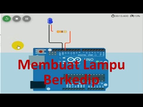
Program Arduino Lampu Kedip Secara Online Gunakan WOKWI Tutorial DIY @tptumetro
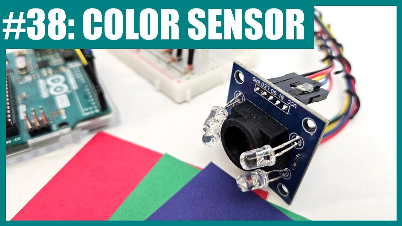
How to Use a TCS3200 Color Sensor with Arduino (Lesson #38)

Arduino: Toggle a LED using Direct Port Manipulation #arduino #arduinoide

Tutorial Dasar Relay Arduino

Cara Remote Komputer dari HP dengan Chrome Remote Desktop
5.0 / 5 (0 votes)
