SR Flip Flop to JK Flip Flop Conversion
Summary
TLDRThis educational video script guides through the conversion of an SR flip-flop to a JK flip-flop, a crucial topic for exams. It outlines a five-step process: identifying available and required flip-flops, creating a characteristic table for the JK flip-flop, determining the excitation table for the SR flip-flop, deriving S and R values using a K-map, and implementing the changes with AND gates. The script emphasizes the importance of following each step accurately to avoid mistakes and achieve the correct conversion.
Takeaways
- 📘 The video script is about converting an SR flip-flop to a JK flip-flop using a five-step process.
- 🔍 Step one emphasizes the importance of correctly identifying the available (SR) and required (JK) flip-flops to avoid confusion.
- 📊 In step two, the characteristic table for the JK flip-flop is created, which is essential for determining the next state of the flip-flop.
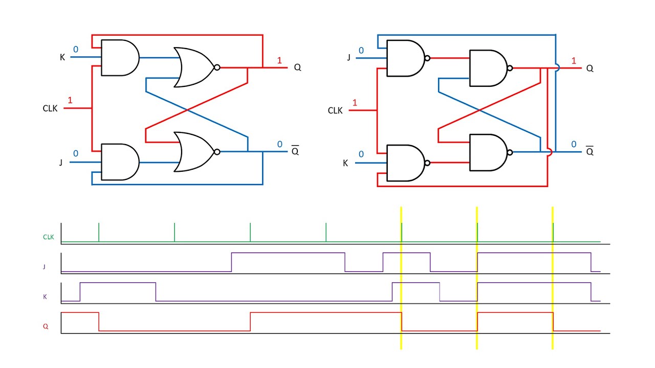
- 🔄 The characteristic table shows the next state (q n+1) based on the current state (q) and the inputs J and K.
- 📝 Step three involves creating an excitation table for the available SR flip-flop, which helps in understanding the inputs required for the desired state changes.
- 🗂 The excitation table for the SR flip-flop is simplified to only four combinations instead of eight, making it easier to fill and understand.
- 🔑 Step four uses a K-map to determine the Boolean expressions for S and R inputs of the SR flip-flop based on the JK flip-flop's characteristic table.
- 🔍 The K-map simplifies the process of finding the expressions for S and R by grouping 1s and avoiding the involvement of 'don't care' conditions.
- 🔧 The final step is the implementation of the derived Boolean expressions to modify the SR flip-flop into a JK flip-flop using AND gates.
- 🛠️ The implementation involves connecting the outputs of the SR flip-flop (q and q') with the inputs J and K through AND gates to achieve the desired functionality.
- 📚 The script concludes by highlighting the importance of following all five steps to correctly convert an SR flip-flop to a JK flip-flop.
Q & A
What is the main topic of the video script?
-The main topic of the video script is the conversion of an SR flip-flop to a JK flip-flop using a five-step process.
Why is it important to determine the available and required flip-flops correctly?
-It is important to determine the available and required flip-flops correctly because if they are switched, the entire conversion process will be reversed, leading to an incorrect answer.
What is a characteristic table and why is it needed for the JK flip-flop?
-A characteristic table is a table that defines the next state of a flip-flop based on its current state and input conditions. It is needed for the JK flip-flop to understand the behavior of the flip-flop in different input scenarios.
What are the four possible combinations for the excitation table of an SR flip-flop?
-The four possible combinations for the excitation table of an SR flip-flop are when both S and R are 0, when S is 0 and R is 1, when S is 1 and R is 0, and when both S and R are 1.
What does 'q n plus 1' represent in the context of flip-flops?
-'q n plus 1' represents the next state of the flip-flop, which is the state it will transition to based on the current state and input conditions.
How is the excitation table for an SR flip-flop constructed?
-The excitation table for an SR flip-flop is constructed by listing all possible combinations of the current state (q) and the next state (q n plus 1), and then determining the inputs S and R that would result in those transitions.
What is the purpose of a K-map in the conversion process?
-The purpose of a K-map (Karnaugh map) in the conversion process is to simplify and minimize the Boolean expressions for the S and R inputs of the SR flip-flop, making it easier to determine the equivalent JK flip-flop inputs.
What are the Boolean expressions for S and R obtained from the K-map?
-The Boolean expressions for S and R obtained from the K-map are S = Q'J and R = QnK, where Q' is the complement of Q, and n represents the current state.
How can an SR flip-flop be converted to a JK flip-flop using logic gates?
-An SR flip-flop can be converted to a JK flip-flop by using two AND gates. The inputs to these gates are determined by the Boolean expressions for S and R, and the outputs of the gates are used to replace the S and R inputs of the original SR flip-flop.
What is the significance of the five-step process in converting an SR flip-flop to a JK flip-flop?
-The five-step process is significant as it provides a structured and systematic approach to converting an SR flip-flop to a JK flip-flop, ensuring that all necessary considerations are accounted for and reducing the likelihood of errors.
Outlines

Этот раздел доступен только подписчикам платных тарифов. Пожалуйста, перейдите на платный тариф для доступа.
Перейти на платный тарифMindmap

Этот раздел доступен только подписчикам платных тарифов. Пожалуйста, перейдите на платный тариф для доступа.
Перейти на платный тарифKeywords

Этот раздел доступен только подписчикам платных тарифов. Пожалуйста, перейдите на платный тариф для доступа.
Перейти на платный тарифHighlights

Этот раздел доступен только подписчикам платных тарифов. Пожалуйста, перейдите на платный тариф для доступа.
Перейти на платный тарифTranscripts

Этот раздел доступен только подписчикам платных тарифов. Пожалуйста, перейдите на платный тариф для доступа.
Перейти на платный тарифПосмотреть больше похожих видео
Latches and Flip-Flops 6 - The JK Flip Flop

Introduction to JK Flip Flop | JK flip flop full explanation | Digital Electronics
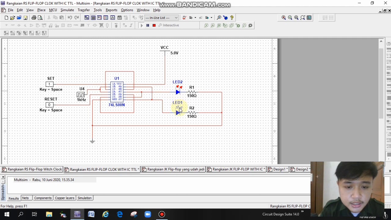
Simulasi Rangkaian JK Flip-flop, RS Flip-flop, dan D Flip-flop ( Faishal Satria G 2211181006 )

SAYISAL ELEKTRONİK DERSLERİ: JK Flip Flop
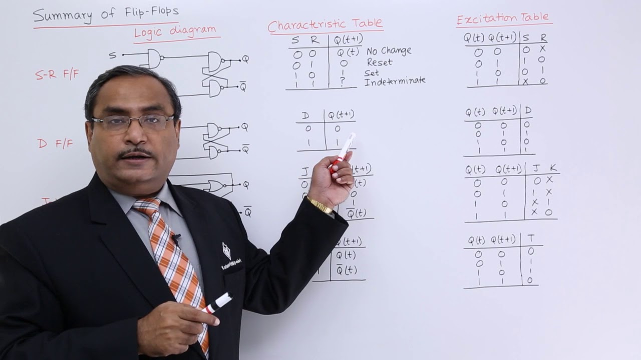
Summary of all Flip-Flops
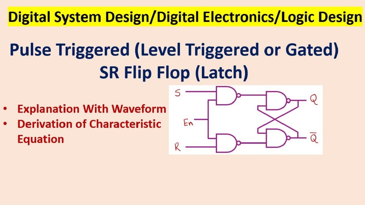
Pulse Triggered (Level Triggered or Gated) SR Flip Flop (Latch)
5.0 / 5 (0 votes)
