ejemplo superposición c a
Summary
TLDRThe video script discusses the method of superposition in electrical circuits, focusing on calculating the voltage across a specific point labeled 'v2'. It explains the process of analyzing the circuit with a single source at a time, calculating the current through various impedances using Ohm's law and the current divider rule. The script involves converting impedances to polar form, applying the method to alternating current, and obtaining the resultant voltage by superposing the effects of different sources. The explanation includes mathematical calculations and the use of complex numbers to find the final voltage in rectangular form.
Takeaways
- 🔌 The method of superposition is used to solve for voltages and currents in a circuit with multiple sources.
- 🔍 The script focuses on finding the voltage V2 at specific points in a circuit with complex impedances.
- 🔧 The first step involves analyzing the circuit with respect to the first voltage source, treating it as an open circuit for the other sources.
- 📡 The script describes a scenario with a current source and impedances in parallel, requiring the use of current division theorems.
- 🔢 The current I2 is calculated using the total current from the source and the impedances involved, applying Ohm's law for AC circuits.
- 📚 Impedance values are converted to polar form for calculation, which includes magnitude and phase angle.
- 🔗 The voltage V2 across an impedance is found by multiplying the current through that impedance by its impedance value.
- 🔄 The process is repeated for a second source, considering the circuit with respect to this new source and calculating the resultant voltage.
- 📉 The equivalent impedance of the circuit is recalculated when considering different sources, which affects the current and voltage calculations.
- 📌 The final voltage V2 is obtained by superposing the voltages calculated with respect to each individual source.
- 📝 The script emphasizes the importance of checking calculations, especially when converting between rectangular and polar forms of complex numbers.
Q & A
What is the method being discussed in the script?
-The method being discussed is the method of superposition.
What is the first step in applying the method of superposition according to the script?
-The first step is to work with one source at a time, starting with the first source.
What is the main objective of the exercise in the script?
-The main objective is to find the voltage V2 at certain points in the circuit.
What is the significance of the term 'circuito abierto' in the script?
-'Circuito abierto' refers to an open circuit, which is a condition where the circuit is broken and no current flows.
What does the script mention about the impedance in the circuit?
-The script discusses the impedance in the circuit, including the calculation of impedance in parallel and the use of impedance in the method of superposition.
How is the current I2 calculated in the script?
-I2 is calculated using the current divider rule, which involves dividing the total current by the sum of the impedances.
What is the significance of converting impedance to polar form in the script?
-Converting impedance to polar form helps in performing complex arithmetic and finding the magnitude and phase angle of the impedance.
What is the role of the current source in the second part of the exercise?
-In the second part of the exercise, the current source is used to find the voltage V2 across the impedance when the direction of the current source is downward.
How is the voltage V2 related to the current I2 in the script?
-V2 is calculated as the product of I2 and the impedance Zc, according to Ohm's law.
What is the final step described in the script for finding the voltage V2?
-The final step is to sum the voltages obtained from both sources, considering their rectangular forms, to get the total voltage V2.
Outlines

Этот раздел доступен только подписчикам платных тарифов. Пожалуйста, перейдите на платный тариф для доступа.
Перейти на платный тарифMindmap

Этот раздел доступен только подписчикам платных тарифов. Пожалуйста, перейдите на платный тариф для доступа.
Перейти на платный тарифKeywords

Этот раздел доступен только подписчикам платных тарифов. Пожалуйста, перейдите на платный тариф для доступа.
Перейти на платный тарифHighlights

Этот раздел доступен только подписчикам платных тарифов. Пожалуйста, перейдите на платный тариф для доступа.
Перейти на платный тарифTranscripts

Этот раздел доступен только подписчикам платных тарифов. Пожалуйста, перейдите на платный тариф для доступа.
Перейти на платный тарифПосмотреть больше похожих видео
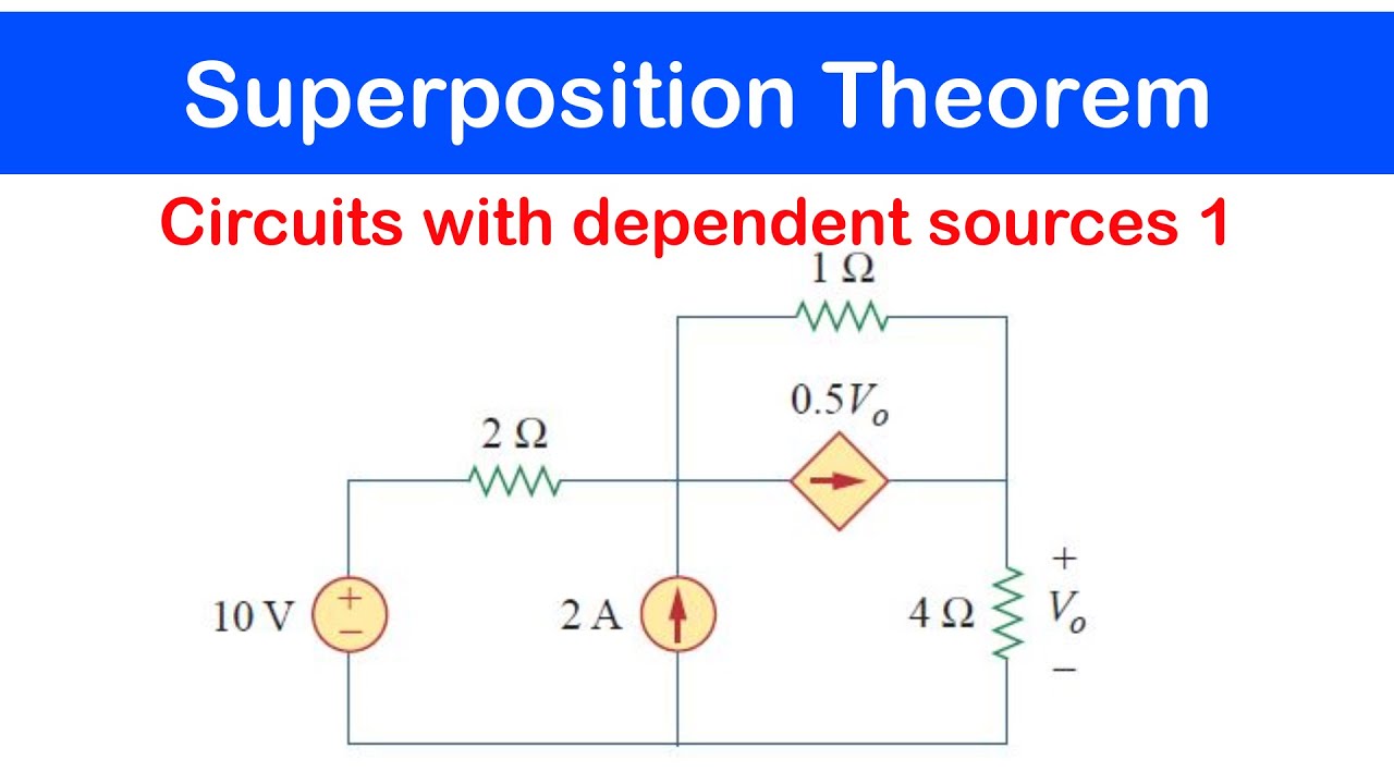
☑️19 - Superposition Theorem: Circuits with Dependent Sources 1
Basic Electrical Engineering | Module 1 | Superposition Theorem (Lecture 06)
Video Pembelajaran Modul 4 & 5 Praktikum Rangkaian Listrik 2024/2025 (FH)

Superposition Theorem (with example)(Unit 1 DC circuits) BEE

Capacitors in Series and Parallel Explained!
A.C. CIRCUIT | A.C. FUNDAMENTALS | COMPLETE STUDY OF PURE A.C. CIRCUITS | LECTURE 3 IN HINDI
5.0 / 5 (0 votes)
