The Op Amp Gyrator Demystified
Summary
TLDRThis video explores the concept of the op-amp gyrator, a simulated inductor used in small-signal applications to replace bulky or expensive physical inductors. The narrator delves into the mathematical derivation of the gyrator’s impedance, explaining its functionality and benefits, such as eliminating inter-winding capacitance. Practical applications include high-pass filters, audio equalizers, and resonant circuits. The video also walks through the design process for a gyrator-based filter, offering insights into component selection and frequency tuning. The simplicity and versatility of the gyrator make it a valuable tool for electrical engineers, especially in analog circuit design.
Takeaways
- 😀 The op-amp gyrator is a simulated inductor used in small signal applications to replace real inductors, especially in resonant circuits.
- 😀 A major advantage of the gyrator over real inductors is the absence of inter-winding capacitance and its ability to be much smaller and cheaper.
- 😀 The gyrator model includes a series resistance that simulates the effective series resistance (ESR) of real inductors, useful in resonance circuits to adjust the quality factor (Q).
- 😀 The op-amp gyrator is limited in its frequency of operation by the op-amp, making it unsuitable for RF applications or high-power uses.
- 😀 One common application of the gyrator is in RL high-pass filters, where it can replace inductors in a filter circuit to simplify the design.
- 😀 In graphic equalizers, the gyrator can simulate inductance in RLC circuits, enabling more compact and cost-effective designs.
- 😀 The gyrator is especially useful in analog audio systems, where it acts as an inductor in an RLC resonator circuit for equalization.
- 😀 The gyrator circuit includes a series resistor, and the capacitor is the only external component, making the design more straightforward.
- 😀 The script provides a detailed, step-by-step derivation of the mathematical formulas for the gyrator, offering clarity on its operation and design.
- 😀 The passive equivalent impedance of the gyrator can be mathematically derived and set equal to the active circuit's impedance to solve for the component values like R1, R2, and C1.
- 😀 The script concludes by demonstrating how to design a band reject filter using the gyrator, showing how to calculate component values for a specific filter performance, such as a 20dB projection at 1kHz.
Q & A
What is an Op-Amp Gyrator and how does it simulate an inductor?
-An Op-Amp Gyrator is an active circuit that uses an operational amplifier (op-amp) to simulate the behavior of an inductor. It replaces a physical inductor with an equivalent active circuit, making it useful in applications where a real inductor would be impractical or expensive.
Why is the Op-Amp Gyrator useful in small-signal applications?
-The Op-Amp Gyrator is particularly useful in small-signal applications because it allows for the simulation of inductance in circuits without requiring a large, bulky, and expensive inductor. It is ideal for low-frequency applications where inductance is needed but a real inductor would be too large or costly.
What is the key limitation of the Op-Amp Gyrator?
-The main limitation of the Op-Amp Gyrator is that one end of the simulated inductor must be connected to ground. Additionally, the frequency of operation is limited by the op-amp itself, meaning it cannot be used in RF (radio frequency) applications.
How does the series resistance in a gyrator compare to that of a real inductor?
-The series resistance in a gyrator mimics the effective series resistance (ESR) of a real inductor, representing the internal losses in the inductor. This resistance is crucial for adjusting the quality factor (Q) of the resonant circuit, although in the gyrator, it is often designed to be large enough that it has minimal effect on the overall operation.
What is the significance of the frequency limitation in the gyrator's design?
-The frequency limitation in the gyrator design is due to the op-amp's performance characteristics. Since op-amps cannot function effectively at very high frequencies, the gyrator is limited to low-frequency applications, making it unsuitable for RF and high-power applications.
How does the Op-Amp Gyrator help in the design of a high-pass filter?
-The Op-Amp Gyrator can replace a physical inductor in an RL high-pass filter design. By using the gyrator, the inductor’s role is simulated, allowing for a more compact and cost-effective solution while maintaining the same frequency response characteristics as the original RL filter.
What is the advantage of using the Op-Amp Gyrator in a graphic equalizer?
-In a graphic equalizer, the Op-Amp Gyrator is used to simulate inductors in resonance circuits. The gyrator's series resistance can be adjusted to modify the quality factor (Q) of the circuit, allowing for precise control over the boost or cut of audio frequencies. This makes it an efficient and reliable component in analog equalizer designs.
What is the role of the capacitor in the gyrator circuit used for high-pass filtering?
-In the gyrator circuit used for high-pass filtering, the capacitor plays a crucial role in determining the cutoff frequency. The gyrator’s simulated inductance, along with the capacitor, forms a high-pass filter where the capacitor allows high-frequency signals to pass while attenuating low frequencies.
How do the mathematical formulas for the gyrator simplify the design process?
-The mathematical formulas for the gyrator, once derived, provide a straightforward way to calculate the necessary component values (such as resistance, capacitance, and inductance) for specific filter designs. These simplified equations eliminate the need for complex calculations, making it easier for engineers to design effective circuits quickly.
Why was the author initially confused about the gyrator equations, and how was the confusion resolved?
-The author was initially confused about the gyrator equations due to topographical errors in a reference book they were using. After correcting these errors, the equations became clear, and the derivation process made sense, ultimately leading to a better understanding of the gyrator’s operation and applications.
Outlines

Этот раздел доступен только подписчикам платных тарифов. Пожалуйста, перейдите на платный тариф для доступа.
Перейти на платный тарифMindmap

Этот раздел доступен только подписчикам платных тарифов. Пожалуйста, перейдите на платный тариф для доступа.
Перейти на платный тарифKeywords

Этот раздел доступен только подписчикам платных тарифов. Пожалуйста, перейдите на платный тариф для доступа.
Перейти на платный тарифHighlights

Этот раздел доступен только подписчикам платных тарифов. Пожалуйста, перейдите на платный тариф для доступа.
Перейти на платный тарифTranscripts

Этот раздел доступен только подписчикам платных тарифов. Пожалуйста, перейдите на платный тариф для доступа.
Перейти на платный тарифПосмотреть больше похожих видео
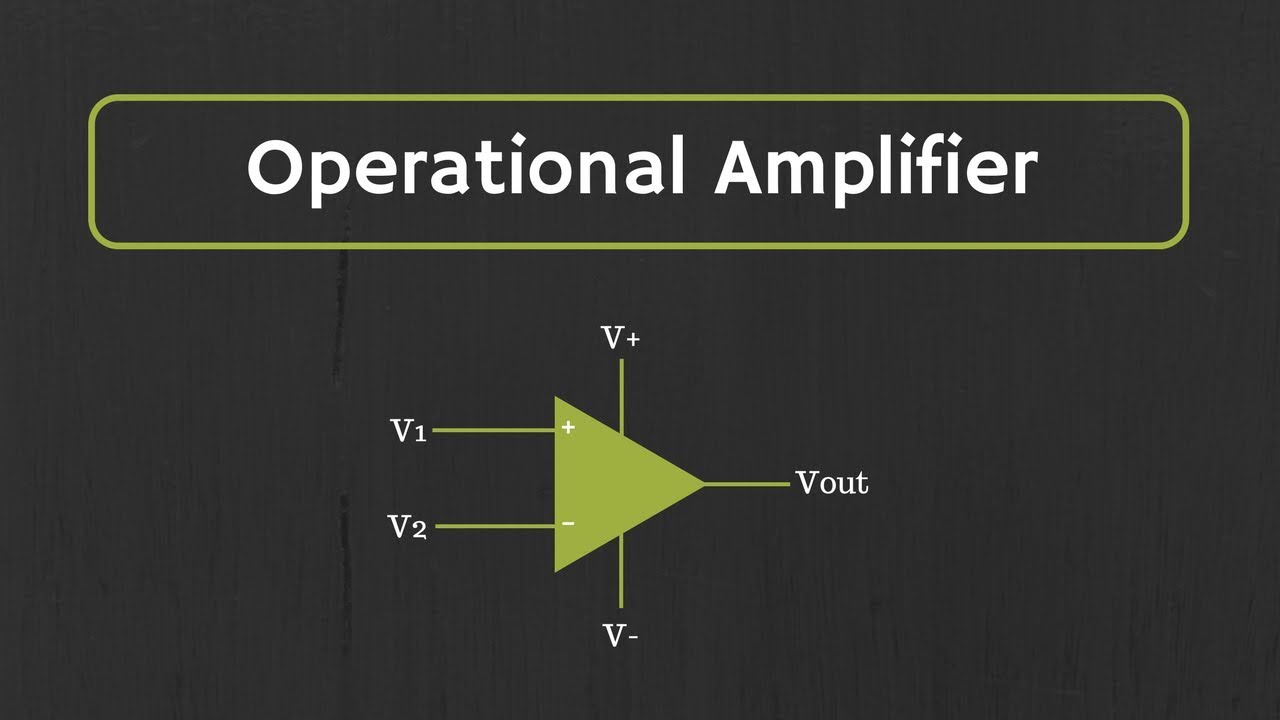
Introduction to Operational Amplifier: Characteristics of Ideal Op-Amp
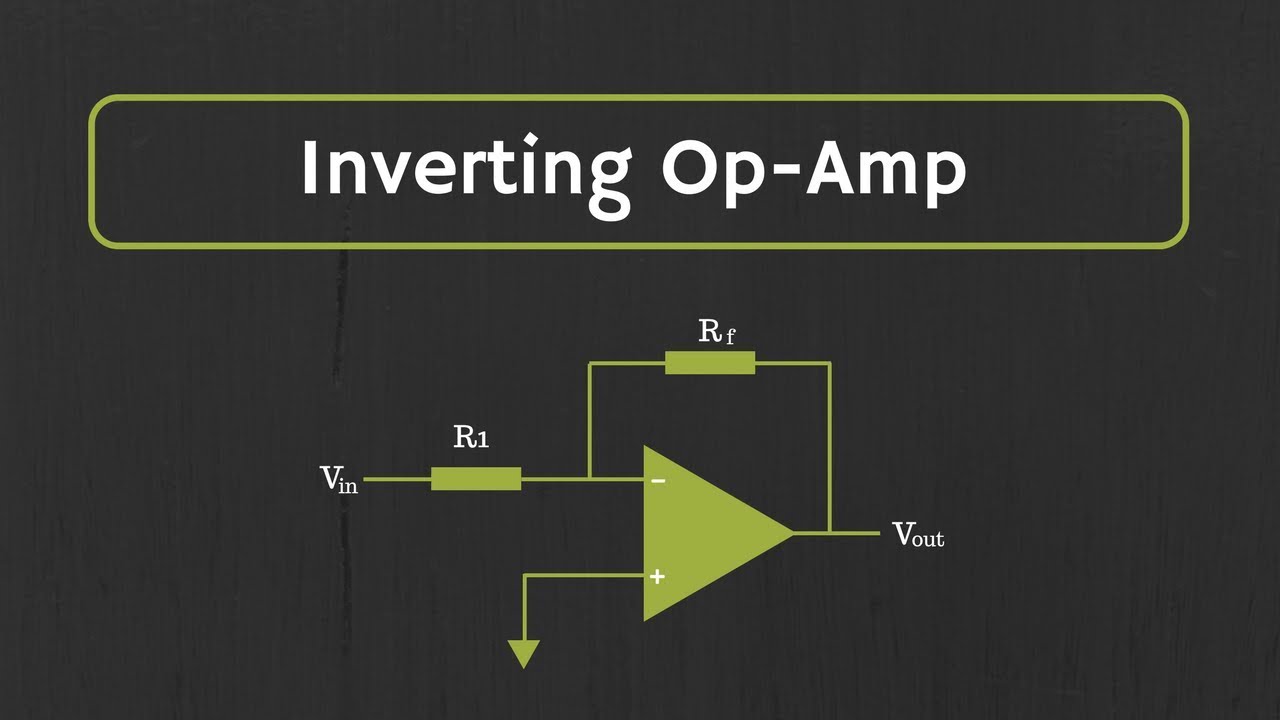
Operational Amplifier: Inverting Op Amp and The Concept of Virtual Ground in Op Amp

Op-Amp: Input Offset Voltage Explained
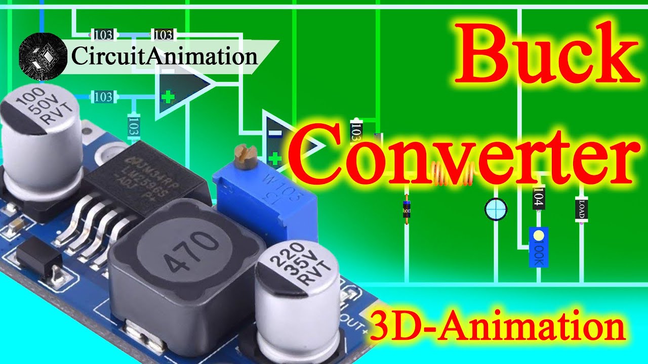
How does Buck Converter work? | DC-DC Converter - 1

#1783 Gyrator (part 3 of 4)

05 0 Openloop Comparator with 2Signals
5.0 / 5 (0 votes)
