Lab1 Rock Young's modulus E and unconfined compression strength UCS
Summary
TLDRThe video explains how to calculate unconfined compressive strength (UCS) and Young's modulus using cylindrical rock samples. The process involves applying axial loads to the sample and measuring the resulting stress and strain. The workflow consists of four steps: measuring the sample, setting up the loading frame, fracturing the rock, and analyzing the data. Key aspects include ensuring sample quality, controlling the loading process, and calculating parameters from force and displacement data. The results yield Young's modulus from loading/unloading cycles and the UCS as the peak stress the rock can withstand.
Takeaways
- 🧱 UCS and junk modulus are calculated using axial load applied to cylindrical cores.
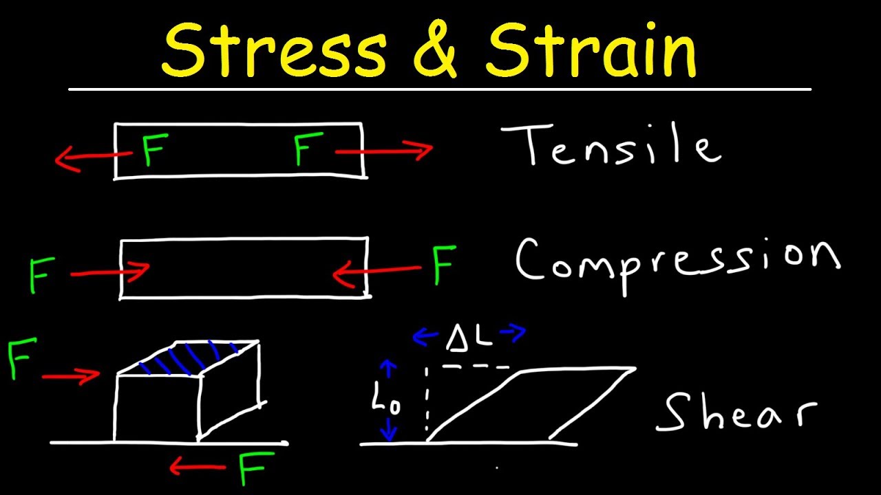
- 📏 Strain is calculated by comparing the change in length (delta L) to the initial length of the sample.
- 📊 Stress is calculated as the applied force divided by the area of the cylindrical sample.
- ⚖️ Junk modulus is determined from the differential stress and differential strain during loading.
- 📈 UCS (unconfined compressive strength) is calculated by finding the peak force the sample can withstand divided by its area.
- 🔍 Step 1 involves measuring and checking the sample’s quality, including verifying if the sample is straight and ensuring the end faces are parallel.
- ⚙️ Step 2 includes setting up the loading frame and confirming that the stress applied is parallel to the sample’s axis.
- 🪨 Step 3 involves fracturing the rock by increasing force and then analyzing the load-displacement data.
- 📑 Step 4 is data analysis, converting force and displacement into stress and strain to calculate the junk modulus and UCS.
- 🔬 The final parameters obtained are junk modulus during loading and unloading and UCS from the peak stress point.
Q & A
What are UCS and Young's modulus, and how are they determined?
-UCS (Uniaxial Compressive Strength) and Young's modulus are determined using cylindrical rock samples. UCS is the maximum stress the sample can withstand before breaking, while Young's modulus measures the stiffness of the rock. Both are determined by applying an axial load to a cylindrical core and calculating stress and strain.
What are the four steps involved in calculating UCS and Young's modulus?
-The four steps are: 1) measuring the sample, 2) setting up the loading frame, 3) fracturing the rock, and 4) analyzing the data.
Why is it important to check the quality of the rock sample before testing?
-It is important to check the quality to ensure the sample is suitable for testing, as samples need to be as close to perfectly cylindrical as possible. Measurements such as the diameter and length are taken to verify uniformity and parallelism of the end faces.
How is stress calculated during the experiment?
-Stress is calculated as the force applied over the cross-sectional area of the cylindrical sample.
How do you determine whether a sample is straight?
-A sample is considered straight if the diameter measurements taken at different parts of the sample are nearly the same. The average of these measurements is used to represent the diameter.
What role does the loading frame play in the experiment?
-The loading frame is used to apply a controlled force to the cylindrical sample. It ensures that the applied stress is parallel to the axis of the sample, and allows the measurement of load and displacement.
What are channels 1 and 3 used for during the experiment?
-Channel 1 is used to measure the load (force) applied to the sample, while Channel 3 measures the vertical displacement of the sample.
What is the purpose of using a protective plastic around the sample?
-The protective plastic is used to prevent injury or damage if the sample fractures and fragments are ejected during the experiment.
How is the Young's modulus calculated during the experiment?
-Young's modulus is calculated as the slope of the stress-strain curve, either during loading or unloading. It is the differential stress divided by the differential strain.
What is the significance of the peak stress in the experiment?
-The peak stress represents the maximum force the sample can withstand before fracturing, which is used to determine the UCS of the rock.
Outlines
🧪 Introduction to UCS and Young’s Modulus Testing Using Cylindrical Samples
In this section, the process of calculating Unconfined Compressive Strength (UCS) and Young’s modulus using cylindrical cores is introduced. The core is placed between two surfaces, and an axial load is applied. As the force compresses the sample, its length shortens, producing strain. Stress is calculated as the force divided by the sample’s area. Young’s modulus is derived from the relationship between stress and strain, while UCS is determined from the peak force the sample can withstand. The process involves four main steps: measuring the sample, setting up the loading frame, fracturing the rock, and analyzing the data.
📏 Measuring and Preparing the Sample
This section details the first step of the process, which involves measuring the sample and conducting quality checks to ensure accuracy. Measurements focus on the diameter to confirm the sample’s straightness and consistency across different points. The length is measured at various angles to ensure parallelism of the sample's end faces, which is critical for applying even force. Additionally, the weight of the sample is recorded. These checks are essential to ensure that force is applied evenly along the axis of the cylindrical sample during testing.
🔧 Setting Up the Loading Frame
In this phase, the setup of the loading frame is explained. The frame's end faces must be aligned to ensure that stress is applied evenly along the sample's axis. Two key parameters are measured: channel 1, which tracks the applied force, and channel 3, which records vertical displacement. The seating speed is used to slowly move the lower part of the frame until the sample is in light contact with the upper frame. Displacement and strain measurements confirm that the sample is correctly positioned for testing. Protective plastic is placed around the sample to ensure safety during fracture.
🚀 Fracturing the Sample
Here, the process of fracturing the rock sample is described. After the initial setup, the displacement speed is used to gradually increase the load until the sample fractures. This process involves cycling the load multiple times to observe the sample’s behavior under both loading and unloading conditions. Once the sample fractures, the test ends, and data collection is stopped. The fracture process provides critical data on how the material responds to stress and when it reaches its breaking point.
📊 Data Analysis and Calculation of Young’s Modulus and UCS
The final step focuses on data analysis. Key measurements include force and vertical displacement, which are used to calculate Young’s modulus and UCS. The initial dimensions of the sample (length and diameter) are used to convert force into stress and displacement into strain. The analysis produces a stress-strain curve, which allows for the calculation of Young’s modulus (during both loading and unloading) as the slope of the curve. The peak stress point, which occurs just before the rock breaks, is used to determine the UCS.
🔍 Conclusion: Calculating Key Parameters
This section concludes the process, summarizing how the three key parameters—Young’s modulus during both loading and unloading, and UCS—are derived from the testing procedure. These parameters provide insight into the material's mechanical properties and its ability to withstand stress before fracturing.
Mindmap
Keywords
💡UCS (Uniaxial Compressive Strength)
💡Young's Modulus
💡Axial Load
💡Strain
💡Stress
💡Loading Frame
💡Fracture
💡Displacement
💡Cylindrical Core Sample
💡Data Analysis
Highlights
Explanation of how to calculate UCS and junk modulus using cylindrical core samples.
Introduction of axial load application over the cylindrical sample to measure strain and stress.
Process of calculating junk modulus by combining differential stress and differential strain.
UCS calculation method as the peak force a sample holds over the area of the cylindrical sample.
Step-by-step workflow: 1) Measure the sample, 2) Set up the loading frame, 3) Fracture the rock, 4) Analyze the data.
Importance of checking the sample for quality control to ensure it's a good cylindrical sample.
Method of measuring diameter at different points of the sample to determine the average diameter.
Ensuring the parallel alignment of the sample's ends to guarantee proper force application.
Detailed instructions on setting up the loading frame, ensuring alignment with levels and bubble indicators.
Explanation of the seating speed and displacement speed during the experiment.
Repetitive loading and unloading to observe how the junk modulus changes.
Observation of force-displacement cycles leading up to the rock's fracture.
Post-experiment analysis of force and displacement data to calculate stress and strain.
Visual observation and data extraction after the rock fractures, including capturing images of the fractured sample.
Final data analysis steps to calculate the junk modulus and UCS from force, displacement, and sample dimensions.
Transcripts
hello everybody
now we are going to
see how we calculate the ucs and
junk modulus using cylindrical cores
so the way that we calculate these two
parameters
are is using uh
an axial load we are going to place
the sample in between
this two sides and we are going to
apply a force over the
cylindrical sample
this sample as we apply the force is
going to get
shorter to
by an amount than tile and that amount
delta l compared to the initial length
that we have is going to give us
the strain that we have this
is going to be combined with the stress
which is calculated as a force over
the area of the cylindrical sample
when we combine strain with stress
we can calculate the junk modulus as a
differential stress
with respect with respect to the
differential
strain that we are applying for the rock
then we can calculate
the ucs as the peak force
that the sample is able to hold over the
area of the
cylinder the workflow that we use to
calculate this
is through four steps
the step one is just to measure the
sample
step two is the setting up
the loading frame the step three is
fracturing the rock
and the step four is the data analysis
and we see that in our first step
we have to not only to measure the
sample but we have to quality check it
to see if actually is a good sample
to perform the measurements
this is because samples are not
perfectly cylindrical
so we have to do some measurements
before
uh using the sample then
first we are going to control the
diameter of the sample
so our first question in here is is the
sample straight
if the sample is straight what we see is
that
measurements are different
parts of the sample
are going to give nearly the same
diameter
and then the diameter of the sample is
going to be the average of them
then we are going to measure the length
with the length we are going to control
as well
if the n faces are parallel
or not this is to ensure that the
force that we are applying is actually
alone is parallel to the axis
of the of the plug that we are using
again we are going to measure at
different angles
and we are going to address the
measurement to obtain an
average length finally
we are going to measure the weight of
the
sample then we are going to
setting up the loading frame so first
we are going to control as well that our
end faces in the loading frame
are parallel one respect to the other
which means
this bottom with this lower part
and then we are going to use a level
just and we have to be sure that the
bubble
on top and at the bottom are having the
same direction
so we ensure that our strain
stress applied is along
is parallel to the axis of the sample
then we are going to
sit the sample to see the sample we have
to
check the parameters that we have to
handle
and the the frame so
when we operate the frame what we are
moving is the
lower part of the frame based on that
we are going to measure two main
parameters
channel one which is the load that we
are
applying in terms of
force and channel 3
which is the displacement which is this
indicates the vertical displacement that
we have with the sample
and then we can choose whether to move
the lower part
either up or down
to increase or decrease the force that
we are
applying over the sample to control the
speed
at which we are moving this
a lower section of the frame we are
going to use the bottom speed
once we click on speed we can see that
we can
change the
speed so f2 is going to be used
just to choose the digit and f3 and f4
are going to use to either
increase or decrease by one
the value of the rate
in these experiments we are going to use
only
two values one value for sitting speed
and one slower value for displacement
speed
so when we want to see the sample we are
going to use the
seating speed the sitting speed
we are going to put in contact
the upper part of the frame with our
sample
without making the actual strain
and contact the
lower part which means that we are going
to move
up until we see that the force
slightly increases this is an indicator
that actually the sample is in contact
with the frames
then we are going to place and hold the
string goes
gauge actually here we are going to see
that the
displacement 2 is going to slightly
increase as well
indicating that we are having
measurements
in both of these channels finally
we are going to place just a protective
plastic around the sample just in case
that it fracture
and explodes we we are
safe from this issue
so the final picture before fracturing
the rock
is this we are going to have the
sampling contact
the string is placed and the protected
plastic
around the sample so once we have
these three aspects example we can start
fracturing the rock
now we are going to follow the same
procedure but
instead of using the set sitting speed
we are going to use the displacement
speed
now we can repeat loading and
uh loading forces to see how junk
modulus
works for during this loading and
unloading process so first we are going
to
increase the force moving up
the bottom and then moving down to see
the unloading
and we are going to repeat this this
cycle a couple of times
and then increase until we fracture the
rock
once we factor the row what we observe
is that we have a
great fourth stroke and then
we can stop our measurement since we are
going to observe that the
rock is tracked once we stop
we can take a picture of the fracture
and we can extract the data file
the fractal rock will look like this
so after we extracted the data and we
clean
all the laboratory we move into the
data analysis what we see is that we are
going to have
many measurements with our respect
to time and where
we have only two channels that are going
to be useful for us
which are force and the displacement two
from these two parameters we are going
to calculate the jam modulus and the ucs
so what we doing here is actually we are
going to filter
only the force and the change in length
and we are going to include now the
initial longitude of the sample and the
diameter of the sample to calculate the
area
based on that we can transform our force
and our vertical displacement into
stress
and vertical strength from this we are
going to see
a plot with this shape
and we can choose
an interval to calculate the gel modes
during either during loading or either
during
unloading as the slope of
the line that we are measuring
finally we can choose the peak stress
which is the point that the rock is
broken as
uh as our ecs
and now that
now we have our three parameters which
is
giant modulus both loading and unloading
and finally the ucs
Посмотреть больше похожих видео
5.0 / 5 (0 votes)