State Of Charge control of Lithium-ion battery in MATLAB/Simulink!
Summary
TLDRThis video demonstrates how to control the charging and discharging of a lithium-ion battery based on its state of charge (SOC). The simulation uses a 7.2V, 5.4Ah battery and a 1000W purely resistive load. The video explains how to set up a simulation in a power GUI block, connect a DC voltage source, and implement an SOC-based control system with an ideal switch and state flow chart. The battery charges and discharges between specified time intervals, and the video provides step-by-step instructions for replicating this simulation. Viewers are encouraged to engage and explore more content.
Takeaways
- 🔋 The video explains how the state of charge (SOC) of a lithium-ion battery can be used to control charging and discharging.
- ⚡ The battery has a nominal voltage of 7.2 volts and a nominal capacity of 5.4 ampere hours.
- 📉 It's advised not to fully charge or discharge the lithium-ion battery to extend its lifespan.
- 🔌 The battery is connected to a resistive load with a power of 1000 watts.
- ⏳ The discharge time is set between 50 seconds to 150 seconds of the simulation.
- 🖥️ A power GUI block is required for the simulation, and the battery must be connected to a DC voltage source with a higher voltage than the battery’s rated 7.2 volts.
- 📊 A state flow chart is used to manage the battery's charging and discharging states based on the SOC parameter.
- 🔄 When the SOC exceeds 80%, the battery stops charging, and if it falls below 40%, it stops discharging and begins charging.
- 🔌 The load is purely resistive with 1000 watts of power, and ideal switches are used to control the charge and discharge timing.
- ⏲️ A clock, compare block, and logic components are used to ensure that the discharge happens only between 50 and 150 seconds of simulation.
Q & A
What is the nominal voltage and capacity of the lithium-ion battery mentioned in the video?
-The nominal voltage of the battery is 7.2 volts, and its nominal capacity is 5.4 ampere-hours.
Why is it advised not to fully charge or discharge a lithium-ion battery?
-It is recommended not to fully charge or discharge a lithium-ion battery to prevent degradation of the battery's lifespan and to maintain its efficiency.
What is the load on the battery, and what type of load is it?
-The load on the battery is 1000 watts, and it is a purely resistive load.
During which time interval does the battery discharge in the simulation?
-The battery discharges between 50 seconds and 150 seconds of the simulation.
What is the purpose of the 'power GUI block' in the simulation?
-The 'power GUI block' is used to set up the simulation environment for simulating power systems, such as the charging and discharging of the battery.
How is the state of charge (SOC) monitored in the simulation?
-The SOC is monitored by using a bus that selects only the SOC parameter from the lithium-ion battery and displays it using a scope.
What does the state flow chart represent in this simulation?
-The state flow chart represents the different charging states of the battery, allowing transitions between charging and discharging based on the SOC level.
What conditions trigger the battery to switch between charging and discharging?
-The battery switches to charging if the SOC is less than 40% and switches to discharging if the SOC is greater than 80%.
How is the load represented in the simulation, and what are its characteristics?
-The load is represented by an RLC load block, and in this case, it is modeled as a purely resistive load with 1000 watts of active power, zero inductance, and zero capacitance.
How does the simulation ensure that the discharge occurs only between 50 and 150 seconds?
-The simulation uses a clock block and compare blocks to define the time interval, ensuring the discharge happens between 50 and 150 seconds, controlled by logic gates and switches.
Outlines

Этот раздел доступен только подписчикам платных тарифов. Пожалуйста, перейдите на платный тариф для доступа.
Перейти на платный тарифMindmap

Этот раздел доступен только подписчикам платных тарифов. Пожалуйста, перейдите на платный тариф для доступа.
Перейти на платный тарифKeywords

Этот раздел доступен только подписчикам платных тарифов. Пожалуйста, перейдите на платный тариф для доступа.
Перейти на платный тарифHighlights

Этот раздел доступен только подписчикам платных тарифов. Пожалуйста, перейдите на платный тариф для доступа.
Перейти на платный тарифTranscripts

Этот раздел доступен только подписчикам платных тарифов. Пожалуйста, перейдите на платный тариф для доступа.
Перейти на платный тарифПосмотреть больше похожих видео
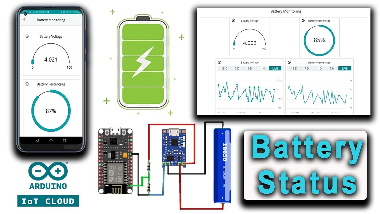
IoT Based Battery Monitoring System Using ESP8266 & Arduino IoT Cloud
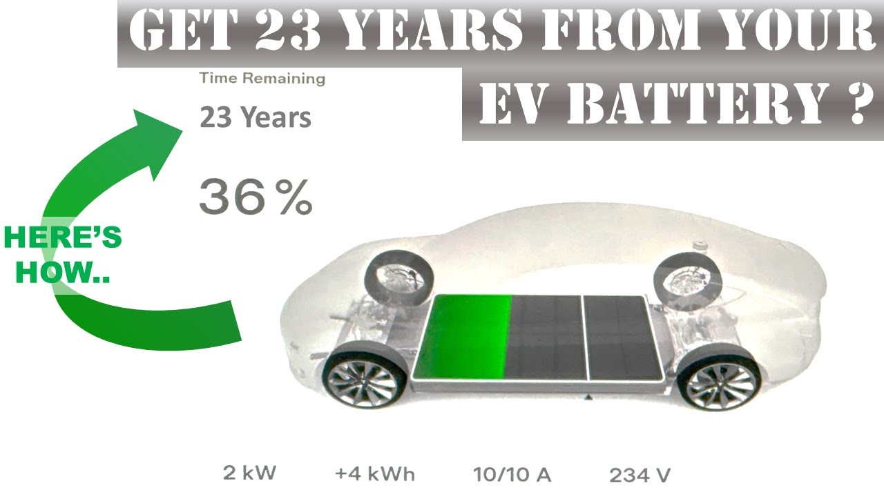
Should I be charging my EV to 90% each day if I only drive a short distance?
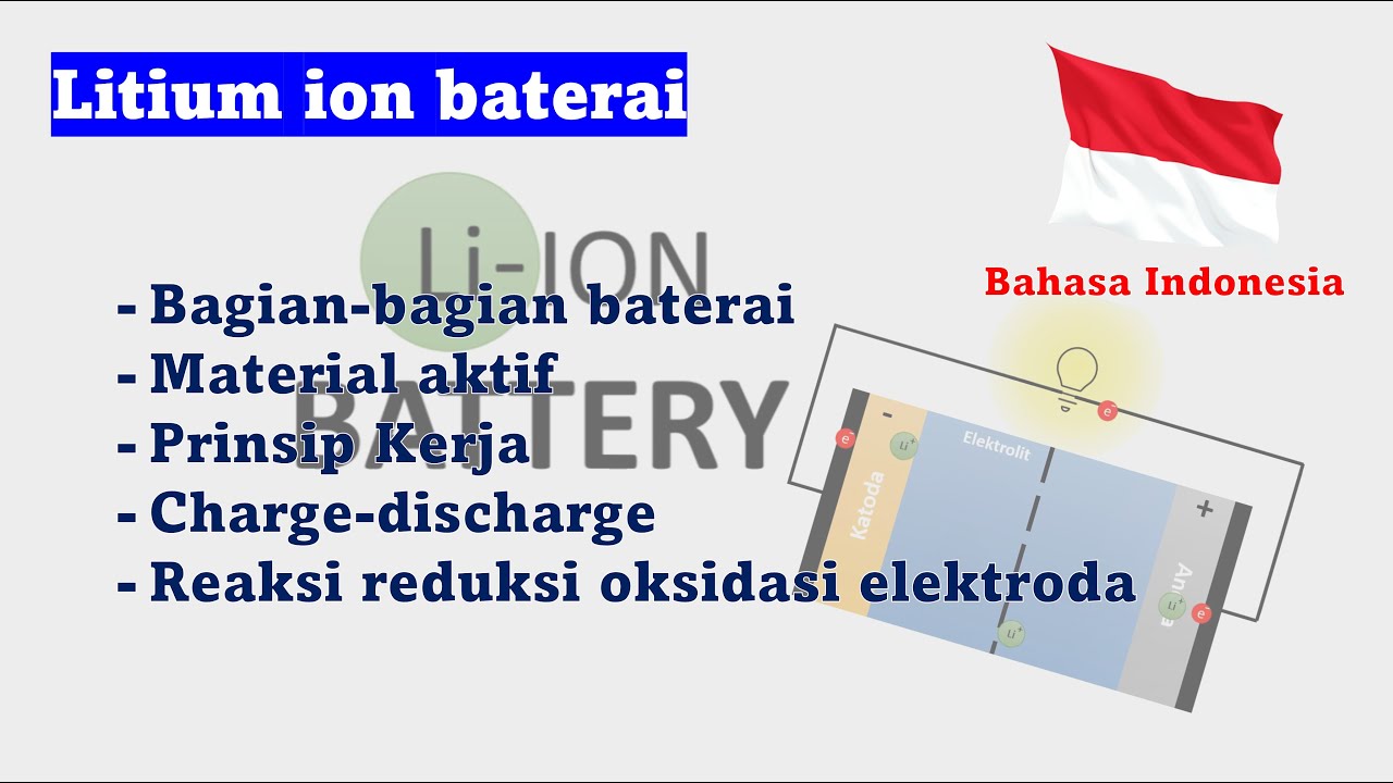
Prinsip Kerja Baterai Lithium Ion: Penjelasan Lengkap dan Mudah Dipahami!
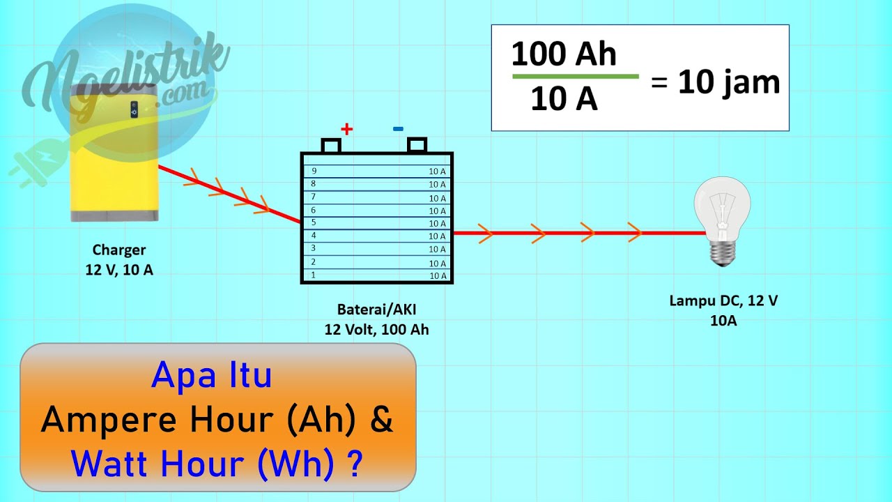
Pengertian Ah (Ampere Hour) Dan Wh (Watt Hour) Pada Aki / Baterai PLTS

Bad charging habits killing your battery? 🪫💀
Calculating the State of Charge of a Lithium Ion Battery System using a Battery Management System
5.0 / 5 (0 votes)
