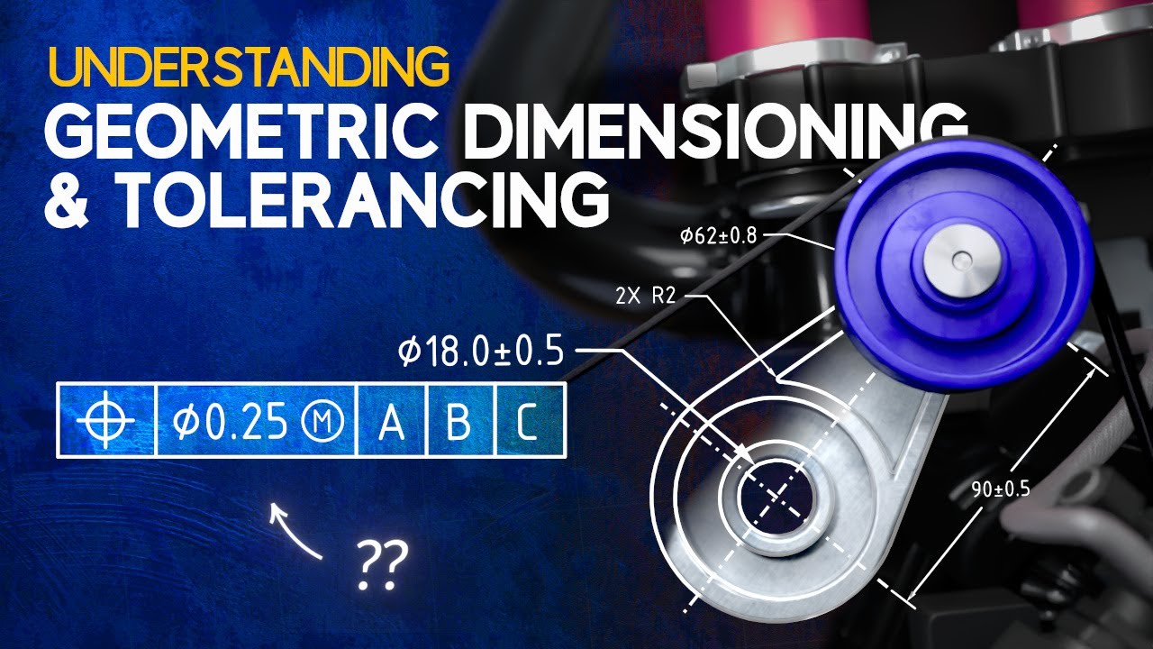
What is GD&T? | GD&T symbols Explained with Example | for Beginners Understanding | Subscribe Us
Summary
TLDRThis video script offers an in-depth exploration of GD&T (Geometric Dimensioning and Tolerancing), a critical system in engineering for defining product geometry. It explains the symbolic language used in engineering drawings to specify allowable deviations in size, shape, and location of features on a part. The script covers various tolerance types, datum systems, and geometric characteristics like straightness, flatness, and cylindricity. It also delves into concepts like MMC, LMC, and fit allowances, essential for ensuring parts function correctly together. The video aims to educate on the importance of precise measurements and specifications in manufacturing.
Takeaways
- 📏 GD&T stands for Geometric Dimensioning and Tolerancing, a system used to define the size, shape, and location of features on a part.
- 🔍 Dimensioning is the specification of the size of features like length, angle, or location, while tolerancing defines the allowable variation in these dimensions.
- 📉 There are three types of tolerances: limit, unilateral, and bilateral, each allowing different permissible variations in feature dimensions.
- 📐 A datum is a theoretical exact feature used as a reference for measurements, with primary, secondary, and tertiary datums controlling different degrees of freedom.
- 📏 Datum features are part features that contact a datum and are denoted with capital letters in boxes, connected to the datum with a triangle.
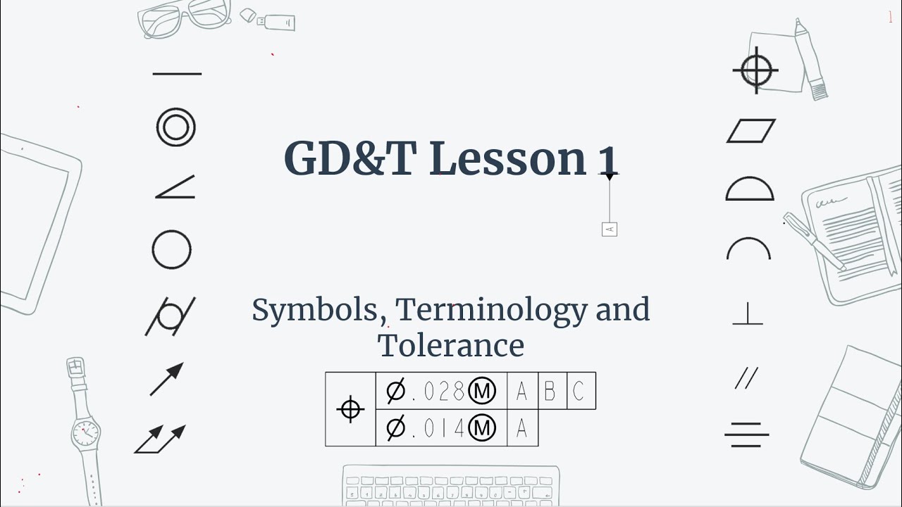
- 🔳 The 14 standard characteristics in GD&T are categorized into form, profile, location, orientation, and run-out types, each with specific control types.
- 🔍 Characteristics like straightness, flatness, and circularity are form type controls that ensure features match their perfect form within a tolerance zone.
- 📏 Profile of a line and surface characteristics are profile type controls that ensure the profile of a feature matches a specified curve or shape.
- 🔄 Orientation type characteristics like parallelism and perpendicularity ensure the correct angular relationship between features and datums.
- 🔄 Run-out type characteristics like circular run-out and total run-out control the form of a surface or the orientation of features in relation to a datum.
- 🔢 MMC (Maximum Material Condition) and LMC (Least Material Condition) are conditions that define the maximum and minimum material states within dimensional tolerances.
Q & A
What does GD&T stand for and what is its purpose?
-GD&T stands for Geometric Dimensioning and Tolerancing. It is a system of symbols, rules, and definitions used to define the size, shape, form, orientation, and location of features on a part. It is used to define the allowable deviation of feature geometry to ensure an object functions correctly.
What are the three types of tolerances mentioned in the script?
-The three types of tolerances mentioned are limit dimension, unilateral, and bilateral. Limit dimensions show the largest and smallest values allowed, unilateral tolerance allows variation in one direction, and bilateral tolerance allows variation in both positive and negative directions.
What is a datum in the context of GD&T?
-A datum in GD&T is a theoretical exact feature from which dimensional measurement is done. It is generally chosen as an edge or feature that has the greatest influence in a specific measurement.
Can you explain the difference between primary, secondary, and tertiary datums?
-Primary datum controls three degrees of freedom, restricting rotation around x and y axes and movement along the z axis. Secondary datum controls two additional degrees of freedom, restricting rotation around the z axis and movement along the y axis. Tertiary datum controls one additional degree of freedom, restricting movement along the x axis.
What is straightness in GD&T and how is it measured?
-Straightness is a form type characteristic that controls the straightness of a feature in relation to its own perfect form. It is measured using a dial indicator by moving its plunger on the surface of the feature in a straight line, and the deflection of the dial gives the actual straightness value.
How is flatness different from straightness in GD&T?
-Flatness, like straightness, is a form type characteristic, but it controls the flatness of a surface in relation to its own perfect form. It is measured using a straight edge and a dial indicator, with the deflection of the dial indicating the actual flatness value.
What is the purpose of the MMC condition in GD&T?
-MMC, or Maximum Material Condition, describes the condition of a feature where the maximum amount of material exists within its dimensional tolerance. It is used to ensure proper fit and function of mating parts.
What does LMC stand for and what does it represent?
-LMC stands for Least Material Condition. It represents the condition of a feature where the least amount of material exists within its dimensional tolerance, which is useful for ensuring maximum clearance or minimum interference.
What is the significance of bonus tolerance in GD&T?
-Bonus tolerance is an additional tolerance for a geometric control applied to a feature of size with MMC or LMC. It allows for more flexibility in the manufacturing process while still meeting the specified tolerances.
How is the virtual condition different from the MMC and LMC conditions?
-Virtual condition is a theoretical extreme boundary condition of a feature generated by the collective effects of MMC size limit, LMC, and any applicable geometric tolerances. It represents the boundary within which any portion of a feature may possibly fall.
What is the purpose of the projected tolerance zone in GD&T?
-The projected tolerance zone is a modifier used for threaded or blind holes to ensure proper fitment of mating parts. It extends the tolerance zone beyond the surface of the part to the functional length of the mating part, controlling the perpendicularity of the hole to the extent of the projection.
Outlines
🔍 Introduction to GD&T
The paragraph introduces the concept of Geometric Dimensioning and Tolerancing (GD&T), a system used in engineering to define the allowable variations in size, shape, and position of features on a part. It explains that GD&T uses a symbolic language on drawings and models to ensure parts function correctly within specified tolerances. The paragraph distinguishes between different types of tolerances: limit dimension, unilateral, and bilateral. It also introduces the concept of datums, which are theoretical exact features used as references for measurement, and explains the role of primary, secondary, and tertiary datums in controlling the degrees of freedom of a part.
📏 GD&T Control Types and Characteristics
This section delves into the various control types and characteristics in GD&T, such as form, profile, orientation, location, and run-out. It explains specific characteristics like straightness, flatness, circularity, cylindricity, and how they relate to the form of a feature. The paragraph also describes how these characteristics are measured using tools like dial gauges and CMM (Coordinate Measuring Machine), emphasizing the importance of ensuring that the measured values fall within the designated tolerance zones.
🔩 Advanced GD&T Concepts
The paragraph discusses advanced GD&T concepts like profile of a line and surface, parallelism, perpendicularity, angularity, concentricity, symmetry, position, circular run-out, and total run-out. It explains how each characteristic is measured and the significance of maintaining tolerances for these measurements. The paragraph also introduces the concepts of Maximum Material Condition (MMC), Least Material Condition (LMC), and bonus tolerance, which are crucial for understanding the extreme material limits of a feature.
🔧 GD&T Tolerances and Fit
This section explores the practical applications of GD&T in ensuring proper fits between mating parts. It explains terms like allowance, clearance, and interference fit, and how they relate to the maximum and minimum material limits of parts. The paragraph also discusses the concept of projected tolerance, which is used for threaded or blind holes to ensure proper fitment with mating parts. Additionally, it touches on the use of the tangent plane and Regardless of Feature Size (RFS) modifier in GD&T.
🛠 GD&T Symbols and Surface Finish
The final paragraph covers various GD&T symbols and their meanings, such as basic dimensions, reference dimensions, all-around symbols, and countersinks. It also explains the concept of surface finish, which includes surface roughness, waviness, and form. The paragraph discusses how surface finish is measured and the different components that contribute to it, such as roughness, waviness, and form. It concludes with a brief overview of how surface roughness is symbolically represented and measured in micrometers.
Mindmap
Keywords
💡GD&T
💡Datum
💡Tolerance
💡Form
💡Profile
💡Orientation
💡Location
💡Run-out
💡MMC and LMC
💡Surface Finish
Highlights
GD&T stands for Geometric Dimensioning and Tolerancing, a system used to define the size, shape, and location of features on a part.
Dimension is a geometric characteristic whose size is specified, such as length, angle, or center distance.
Tolerance is the total permissible variation in size, allowing an object to function correctly.
There are three types of tolerances: limit, unilateral, and bilateral.
Datum is a theoretical exact feature from which dimensional measurement is done.
Primary, secondary, and tertiary datum features control different degrees of freedom of a part.
Geometric characteristics are categorized into form, profile, location, orientation, and run-out types.
Straightness controls the straightness of a feature in relation to its own perfect form.
Flatness controls the flatness of a surface in relation to its own perfect form.
Circularity controls the form of a surface in relation to its own perfect form by independent cross-sections.
Cylindricity controls the form of a variable surface like circularity but applies to the entire surface.
Profile of a line controls the profile at any point of a feature, usually of the current shape.
Profile of a surface controls the profile by describing a three-dimensional tolerance zone around a surface.
Parallelism controls the orientation of a feature nominally parallel to the primary datum of its datum reference frame.
Perpendicularity controls the orientation of a feature normally perpendicular to the primary datum.
Angularity controls the orientation of a feature at a specific angle in relation to its primary datum.
Concentricity controls the central axis of a feature with respect to a datum axis.
Symmetry controls the uniformity of two features on a part across a datum plane.
Position controls the variation of a feature from a specified exit to location.
Circular run-out controls circularity and co-axiality of each circular segment of a surface independently.
Total run-out controls circularity, straightness, co-axiality, and taper of a cylindrical surface about a coaxial datum.
Maximum Material Condition (MMC) and Least Material Condition (LMC) describe the conditions of a feature where the most or least amount of material exists.
Bonus tolerance is an additional tolerance for a geometric control attached to a feature of size with MMC and LMC.
Virtual condition is the theoretical extreme boundary condition of a feature generated by the collective effects of MMC size limits and geometric tolerances.
Allowance is the difference between the maximum material limits of mating parts, indicating the minimum clearance or maximum interference.
Projected tolerance zone is a modifier used for threaded or blind holes to ensure proper fitment of mating parts.
Tangent plane is a simulated plane that contacts the high points of a surface for orientation of the datum.
Regardless of Feature Size (RFS) is a modifier used when the size feature does not affect the specified tolerance.
Basic dimensions are used to describe the exact size, profile, orientation, or location of a feature without involving any tolerance limits.
Surface finish refers to the allowable deviation from a perfectly flat surface made by some manufacturing process.
Transcripts
[Music]
you
let us learn about GD&T basics
what is meant by GD&T GD&T stands for
geometric dimensioning and tolerancing
it is a system of symbols rules and
definitions use it to define the size
shape form orientation and location of
pictures on a part it is a symbolic
language used on engineering drawings
and models to define the allowable
deviation of feature geometry dimension
is a geometric characteristic the size
of which is specified such as length
angle location or center distance etc
tolerance on a dimension is the total
permissible variation in its size which
is equal to the difference between the
limits of size to allow an object to
function correctly now there are three
types of tolerances limit dimension type
unilateral type bilateral time limit
dimensions are two dimensional values
stacked on top of each other these show
the largest and smallest values allowed
anything in between these values is
acceptable
Yury lateral type exists when the target
dimension is given along with the
tolerance that allows variation to occur
in only one direction a bilateral
tolerance exists if variation from a
target dimension is shown occurring in
both the directions positive and
negative if no tolerances are specified
then general tolerances are applied at
the dimension level unless otherwise
specified now let us learn some basic
concepts data a datum is a theoretical
exact feature from which dimensional
measurement is done which is generally
chosen as an edge or feature which has
the greatest influence in a specific
measurement a datum feature is a part
feature that contacts a data it is
denoted with the capital alphabetic
letters these letters are in boxes and
tied to the datum feature with the black
color field triangle as shown below
there are three types of datum and all
are perpendicular to each other primary
datum secondary datum and tertiary data
its presence shown in the below example
of feature of control plane
primary data the primary datum feature
has at least three points of contact
with its datum plane it controls three
degrees of freedom of the feature means
three degrees of freedom are restricted
that is rotation around x axis rotation
around y axis movement along the z axis
secondary data the secondary datum
feature has at least two points of
contact with its datum plane it controls
two additional degrees of freedom of the
feature means two additional degrees of
freedom are respected rotation around z
axis moment along the y axis tertiary
datum the tertiary datum feature has at
least one point of contact with this
datum plane it controls one additional
degree of freedom of the picture means
one additional degree of freedom are
restricted that is movement along the x
axis these are the putting standard
characteristics and their symbols of
GD&T these fourteen characteristics fall
into five different control types they
are form profile location orientation as
a note let us learn about straightness
characteristic it's control category
form type and it controls straightness
of a feature in relation to its own
perfect form in the given example
tolerance zone of point one of
cylindrical future will be measured
using Dale gates by moving its plunger
on the surface of the pitcher in a
straight line and deflection of the dial
gives actual straightness value that
value should be within the tolerance
zone
let us discuss about flatness
characteristic its control category form
type and it controls the flatness of the
surface in relation to its own perfect
form in the given example total zone of
point 1 of the rectangular feature will
be measured using tail gauge by moving
its leaver plunger on the surface of the
pitcher which is located on the two
identical B blocks as shown in the
picture and deflection of the dial gives
actual flatness value that value should
be within the tourist zone let us learn
about circularity characteristic its
control category form type and contours
the form of varivolt surface in relation
to its own perfect form by independent
cross-sections in a given example
tolerance on 0.1 of the cylindrical
feature will be measured using dial
gauge by moving its plunger on the
surface of the pier in a circular
direction which is located on the two
identical B blocks as shown in the
picture and deflection of the dial gives
actual circularity value that value
should be within the tolerance zone let
us go through cylindricity
characteristic its control category from
type and controls in the form of
variable surface like circularity but
apply simultaneously to entire surface
in the given example tolerance zone of
0.005 of the cylindrical feature will be
measured using dial gauge by moving its
plunger on the entire surface of the
future in a circular direction which is
located on the two identical B blocks as
shown in the picture and the deflection
of seed oil gives actual cylindricity
value that value should be within the
tolerance zone selection of points on
the cylindrical surface based on
tightness of the tolerance
let us go through profile of the line
characteristic its control category
profile type and controls the profile of
the line at any point of the future
usually of the current shape in the
given example torrent zone 0.25 of the
curvature will be measured using del
gauge by moving its plunger on the
surface of the creature by keeping
master profile as reference for the
moment as sure in the picture and
deflection of the del gives actual
profile of the line value that value
should be within the tolerance zone
let us study profile of a surface
characteristic its control category
profile type and controls the profile of
the surface by describing a
three-dimensional tolerance zone around
a surface usually it is an advanced
curve or shape in the given example
total zone 0.25 of the carbon future
will be measured using CMM by moving its
probe on the surface of the future by
taking necessary reference points as
shown in the picture and automatically
calculates actual profile of the surface
value that value should be within the
tolerance zone here CMM is a coordinate
measuring machine used for measuring the
physical geometrical characteristics of
an object its probe will measure the
different characteristics by taking
necessary preference points rows may be
mechanical optical laser or white light
etc this machine takes readings in 6
degrees of freedom and displays those on
the computer monitor
let us study about parallelism
characteristic its control category
orientation type and controls
orientation of a feature it is nominally
parallel to the primary datum of its
datum reference frame in the given
example the order in zone of point one
of the rectangular feature will be
measured with respect to datum a using
del gauge by moving its liver plunger on
the surface of the creature which is
placed on the another respective surface
as shown in the picture and deflection
of the del gives actual parallelism
value with respect to datum a that value
should be within the tolerance zone let
us learn about perpendicularity
characteristic its control category
orientation type and controls
orientation of a picture which is
normally perpendicular to primary datum
of its datum reference frame in the
given example tolerance zone of point
one of the pitcher will be measured with
respect to datum a which is clamped on
the you clamp B block using L cage by
moving its plunger in perpendicular
direction of the surface of the picture
as shown in the picture and deflection
of the Dell gives actual
perpendicularity value with respect to
datum a that value should be within the
tolerance zone
[Music]
let us discuss about angularity
characteristic its control category
orientation type and controls
orientation of the creature at a
specific angle in relation to its
primary datum of its datum reference
frame in the given example tolerance
zone of point 2 pi of the feature will
be measured with respect to datum a by
using dial gauge by moving its plunger
in a straight line which is located on
this sign bar and click page setup as
shown in the picture and deflection of
the del gives actual angular ative value
with respect to datum a that value
should be within the tolerance zone let
us study about concentricity
characteristic its control category
location type and controls the central
axis of reference in future P a datum
axis it is also called as Co actually in
the given example tolerance zone of
point one of the cylindrical feature
will be measured with respect to datum a
using dial gauge by moving its plunger
on the surface of the creature in a
circular direction by rotating reference
or respective portion of the pitcher
which is located on the B block as shown
in the picture and deflection of the
dial gives actual concentricity value
with respect to a that value should be
within the tolerance zone let us go
through symmetrical check its control
category location type and controls
uniformity of two features on a part
across a datum plane in the given
example Jordan zone of 0.05 of the
pitcher will be measured with respect to
datum a using Bell gauge by moving it
sliver plunger on the surface of the
pitcher BC first place it on one surface
then another as shown in the picture a
deflection of the dial gives actual
Symetra value with respect to a that
value should be within the tolerance
zone
[Music]
let us learn the board position
characteristic its control category
location type and controls variation of
the feature from a specified exit to
location the given example tolerance
zone of 0.1 at maximum it'll condition
of the feature will be measured with
respect to datums a b and c using c mm
probe by taking reference points of the
feature as shown in the picture and
automatically calculates actual position
value with respect to datum a b and c
that value should be within the
tolerance zone let us study circular
run-out characteristic it's control
category run-out type and control
circularity and co actuality of each
circular segment of the surface
independently about the coaxial data in
the given example tolerance zone of
point one of the picture will be
measured using dial gauge by moving its
plunger on any ponta feature with
respect to datum a which will be rotated
by placing it on the b block as shown in
the picture and deflection of the dial
qs and actual circular are not value
that value should be within the
tolerance zone
let us learn about total run-out
characteristic it's control category
run-out type and control circularity
straightness Co actuality and taper of
the cylindrical surface about a coaxial
data the given example torrid zone of
0.05 of the future will be measured
using bail gauge by moving its plunger
on the entire surface of the pitcher
with respect to datum a which will be
rotated by placing it on the B block as
shown in the picture and deflection of
the Dell gives an actual total run Note
value that value should be within the
tolerance zone maximum material
condition MMC MMC describes the
condition of a feature where maximum
amount of material exists within its
dimensional tolerance this condition
exists at minimum clearance or maximum
interference example largest pin
diameter smallest hole size in the
picture you can see that shaft with the
diameter 10 mm width Dalton's pass or
minus 0.1 mm C is equal to ten point one
and for the hole diameter 10 mm plus or
minus point one tolerance mm C is equal
to nine point nine mm least material
condition LM c LM C describes the
condition of a feature where the least
amount of material exists within its
dimensional tolerance this condition
exists at maximum clearance or minimum
interference examples smallest pin
diameter largest hole diameter in the
following example we can see that shaft
with the diameter 10 mm plus or minus
point 1 tolerance LM C is equal to nine
point nine mm and for the hole diameter
10 mm plus or minus point one tolerance
LM C is equal to ten point one mm
bonus codons bonus tolerance is an
additional tolerance for a geometric
control it is the additional tolerance
available for a geometric control attach
it to a feature of size with MMC maximum
mental condition and LMC least material
condition modifier so bonus tolerance is
equal to shaft size MMC
- shaft says at LMC example chopped-up
diameter 25 plus or minus 3 here at MMC
shaft size is equal to diameter 28 so
bonus tolerance is 0 for shaft size
diameter 27 bonus tolerance is 1/4 shop
size diameter 26 bonus tolerance is 2
and so on so total bonus tolerance is
equal to MMC - LM C that is diameter 28
- diameter 22 that is equal to 6
let us discuss about virtual condition
virtual condition is the theoretical
extreme boundary condition of a feature
of size generated by the collective
effects of MMC size limit of the teacher
and any applicable geometric tolerances
in the below figure of hole of diameter
10 plus or minus 0.2 the MMC is equal to
9 point 8 the worst case would be the
smallest hole that is also out of
position that is 9 point 8 - point 3
that is equal to nine point five this
case is called virtual condition
condition this is similar to virtual
condition but considers least material
condition of the feature that is least
metal condition plus stated geometrical
tolerance plus bonus that is equal to
ten point two plus point three plus
point four that is equal to ten point
nine this represents barrier where any
portion of the holes age may possibly
fall allowance allowance is defined as
the difference between the maximum
material limits of the mating parts xi
is the minimum clearance or maximum
interference between mating parts that
is equal to MMC hole - mm C sharp
clearance clearance is the loosest width
or maximum intended difference between
hitting parts that is equal to l MC hole
- l MC shop let us discuss about
different types of its clearance width
the tolerance of the parts is such that
the largest shaft is smaller than the
smallest hole in this one part fits
easily into another with the resulting
clearance gap in this picture we can see
the powders on the shop is equal to zero
point zero zero two and tolerance on the
hole is equal to zero point zero zero
two minimum clearance 0.66 zero minus
point 6 5 5 that is equal to zero point
zero zero five and maximum clearance
zero point six six two minus zero point
six by 3 that is equal to zero point
zero zero nine interference fit in this
type one part must be forcefully fitted
into another that is maximum clearance
is always negative in this example we
can see that orders on shop is equal to
zero point zero zero one and tolerance
on the whole is equal to zero point zero
zero one minimum clearance is equal to
0.51 zero minus point five one three
that is equal to minus zero point zero
zero three inch that is the tightest fit
0.003 in interference maximum clearance
that is equal to point five one one
minus point 5 1 2 that is equal to minus
0.001 in the loosest bit 0.001 in
interference
transition fit the tolerance of the
parts is such that the allowance is
negative and the maximum clearance is
positive a transition pit exists when
the maximum clearance is positive and
minimum clearance is negative in this
example tolerance on the shaft is 0.005
and tolerance on the hole is 0.005
minimum clearance that is equal to 0.51
zero by the zero point five one seven
that is equal to minus zero point zero
zero seven inch it is stupid is zero
point zero zero seven in interference
maximum clearance that is equal to zero
point five one five minus zero point 5 1
2 that is equal to zero point zero zero
three in the loser stupid is zero point
zero zero three in clearance let us
learn about project a tolerance zone the
projected tolerance is a modifier used
for threaded or brisket holes in order
to ensure the proper fitment of the
mating parts by means of studs pins
screws bolts etc the projected tolerance
zone extends above the surface of the
part to the functional length of the pin
stud or screw related to its assembly
with the mating part it controls the
perpendicularity of the hole to the
extent of the projection from the hole
as it relates to the mating part
clearance in the following example let
us take plate with the hole in which a
stud will be inserted with the
positional tolerance with respect to
datum a here you can see that positional
totals of die appoint to apply to the
datum a of lower plate that can be
buried at the worst case within the
mentioned zone as shown in the figure
now it is clear that if the stud axis
follows the worst case then the start
may interfere with the mating plate for
avoiding that interference
specifying the projected tolerance zone
in the drawing is required so here you
can see that projected tolerance of Y
has been mentioned in the drawing after
the value of positional tolerance the
meaning of the projected tolerance of
Phi is in positional tolerance zone of
point 2 will extend by PI units beyond
the surface of the bottom plate
and by doing so interference problem
will avoid
[Music]
tangent plane tangent plane is a
simulated plat plane that contacts the
high points of the surface for
orientation of the data this modifier
indicates that only the tangent plane of
the dormant surface needs to be within
this tolerance zone in the example you
can see the tangent plane selected
within the zone of point three with
respect to datum B for calculation
purposes of parallelism regardless of
feature size our FS RFS is a deport
modifier if no modifier symbol shown in
the picture control which is used when
the size feature does not affect the
specified tolerance it is used and
implied when the geometrical tolerance
is to remain the same no matter what
size hole or shaft is produced within
its tolerance limit in this given
example bonus tolerance point four not
applicable therefore the position of the
shaft must lie in between tolerance zone
of point three regardless of feature
size three state variations restate
variation is a term used to describe
deformation of the part after removal of
forces applied during manufacture
basic dimension it is used to describe
the exact size profile orientation or
location of the future it does not
involve any tolerance limits reference
dimension it is a dimension usually
without tolerance user for reference
purposes only it does not control
production or inspection operations
all-around symbol this indicates the
tolerance applies to surfaces all around
the part dimension origin a circle used
in place of one of the arrowhead when a
dimension line indicates the origin for
measurement conical paper it is used to
indicate paper for conical tapers
this symbol is always shown with
vertical link to the left
slope it is used to indicate slope or
plat tapers datum target it is a
specified point line or area on the part
that is used to establish the datum
reference plane for manufacturing and
inspection operations comfortable this
symbol is used to indicate a counter
bore or a spot phase the symbol precedes
the dimension of the counterbore with no
space countersink this symbol is used to
indicate a countersink the symbol
precedes the dimension of the
countersink with the no space square
this symbol is used to indicate that a
single dimension applies to square shape
this symbol precedes the dimension with
the no space between dipped or deep it
is used to indicate that dimension
applies to the depth of the feature is
simple precedes the depth value with the
no space in between number of places the
X symbol is used along with the value to
indicate the number of times a dimension
or feature is repeated on the drawing
statistical tolerance it is the
assigning of tolerances to the related
components of an assembly on the basis
of statistics by applying statistical
tolerance tolerances of individual
components may be increased or
clearances between mating pearls may be
reduced between this is used to indicate
that a profile tolerance applies to
several contagious features or let
resume designate where the profile
tolerance begins and ends
these letters are reference in using the
between symbol target point this
indicates where datum target point is
dimensionally located on the direct view
of the surface arc length this indicates
that a dimension is an arc length
measured on orbit outline the symbol is
placed above the dimensional tetanus
feature it is used to identify a group
of two or more features of size where
there is a requirement that they may be
treated geometrically as a single
feature of size now let us discuss about
surface finish surface finish is the
allowable deviation from a perfectly
flat surface made by some manufacturing
process surface roughness is a property
of the material surface texture which is
recognized by an uneven topography as
compared to the perfectly applied
surface all machining processes will
generate some rough on the surface since
all the surfaces may not have functional
requirements so no need to have equal
finish everywhere roughness can be
measured by manual comparison against
surface roughness comparator or
profilometer
or optical method surface finish is
broken up into three components such as
roughness waviness and form here
roughness is the machine marks made on
surface by the cutting tool waviness is
the result of vibration of the tool and
form surface irregularities cause is by
one of machine bed or table etcetera
so roughness is the measure of finest
irregularities of the surface venus is
the measure of surface irregularities
with the spacing greater than that of
surface roughness layer refers to the
predominant direction of the surface
texture from this figure you can see
that for a given sample length Aria is
the average variation from mean length R
T is the distance from the highest peak
to the deepest Valley RP is the highest
peak above the mean line RV is the
deepest Valley below the beam line R
that the average RT over given length
example R that is equal to R T 1 plus RT
2 plus RT 3 divided by 3 these are the
symbolic representations of surface
roughness here in the first symbol a
obtained by any production process in
the second symbol a obtained by removal
of material by machining in the third
symbol roughness a obtained without
rimmel of any material in the fourth
symbol a 1 represents upper and a 2
represents lower limit of surface
roughness value in the tip symbol G
represents production method and in
sixth symbol B represents other than our
a value this is the general RA value in
micrometer and it's great number
[Music]
you
[Music]
5.0 / 5 (0 votes)