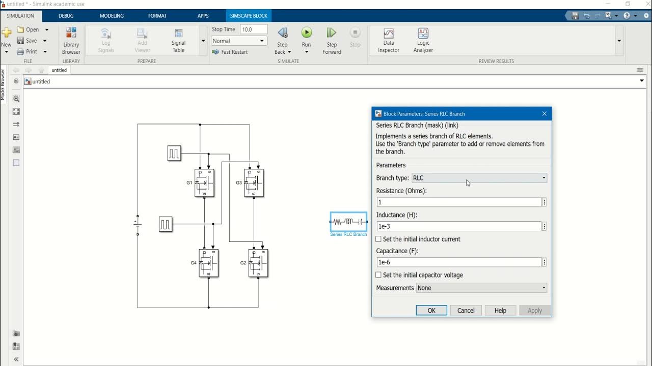
Simulation of a Dual Active Bridge Converter in MATLAB | SIMULINK
Summary
TLDRIn this Electronics Maddy YouTube video, the host demonstrates the simulation of a dual active bridge converter in MATLAB Simulink. The video covers the setup of the DC-to-DC converter, emphasizing its use in voltage transformation and electrical isolation. Key features include its application in vehicle-to-grid systems and the ability to provide both AC and DC power. The tutorial guides viewers through the Simulink model, from selecting components to configuring the circuit, culminating in a successful simulation showing a stable DC output voltage.
Takeaways
- 📹 The video demonstrates the simulation of a dual active bridge converter in MATLAB Simulink.
- 🔌 A dual active bridge converter is a DC-to-DC converter that uses an inverter, transformer, and rectifier to convert DC to AC and then back to DC.
- ⚡ The transformer in the circuit allows for voltage adjustment and provides electrical isolation between input and output, protecting the source in case of load damage.
- 🚗 This type of circuit is commonly used in vehicle-to-grid and grid-to-vehicle applications, particularly for battery charging.
- 🔍 MATLAB Simulink's library browser is used to search and add necessary components like power queue block, DC voltage source, MOSFETs, pulse generators, and a linear transformer.
- 🔄 The video details how to configure the components, including setting the MOSFET connections, transformer parameters, and triggering mechanisms using pulse generators.
- 📏 The correct configuration of the circuit is crucial, especially in connecting the MOSFETs and thyristors to avoid errors and achieve the desired output.
- 📉 Simulation in MATLAB shows that the output voltage is slightly less than expected due to magnetization resistance and inductance in the transformer.
- 🔌 The output waveform from the simulation confirms that the circuit successfully converts DC to a stable DC output with an intermediate AC stage.
- 👍 The video concludes by inviting viewers to ask questions in the comments and to subscribe for more content on similar topics.
Q & A
What is the main topic of the video?
-The main topic of the video is the simulation of a dual active bridge converter in MATLAB Simulink.
What is a dual active bridge converter?
-A dual active bridge converter is a DC to DC converter that uses an inverter to convert DC to AC, a transformer to adjust the voltage, and a rectifier to convert the AC back to DC, with a capacitor for filtering the output voltage.
Why is a transformer used in the dual active bridge converter?
-A transformer is used to increase or decrease the voltage and to provide electrical isolation between the input and output sides of the circuit.
What are some applications of the dual active bridge converter mentioned in the video?
-The dual active bridge converter is used in vehicle-to-grid and grid-to-vehicle applications, particularly as a battery charging section, and can also provide AC supply by tapping from the inverter section.
What is the purpose of the MOSFET in the circuit?
-The MOSFET is used as a switch in the inverter section of the dual active bridge converter to convert DC to AC.
What is the role of the pulse generator block in the simulation?
-The pulse generator block is used to trigger the MOSFETs, operating as an inverter to convert DC to AC.
What is the significance of the phase delay in the pulse generator block?
-The phase delay ensures that the second pair of switches in the inverter starts conducting halfway through the cycle, creating an AC voltage.
Why are thyristors used in the rectifier section of the converter?
-Thyristors are used in the rectifier section because they are commonly used as rectifiers and can handle the natural commutations required for converting AC back to DC.
What is the purpose of the resistive load in the simulation?
-The resistive load is used to simulate the consumption of power in the circuit, allowing the observation of the output voltage waveform.
How is the output voltage measured in the simulation?
-The output voltage is measured using a voltage measurement block connected to a scope, which displays the waveform of the DC output voltage.
What is the expected output voltage in the simulation, and why might it differ from the set value?
-The expected output voltage is approximately 100 volts, but due to drops caused by magnetization resistance and inductance in the transformer, the actual measured voltage might be slightly lower, around 95 volts.
Outlines

このセクションは有料ユーザー限定です。 アクセスするには、アップグレードをお願いします。
今すぐアップグレードMindmap

このセクションは有料ユーザー限定です。 アクセスするには、アップグレードをお願いします。
今すぐアップグレードKeywords

このセクションは有料ユーザー限定です。 アクセスするには、アップグレードをお願いします。
今すぐアップグレードHighlights

このセクションは有料ユーザー限定です。 アクセスするには、アップグレードをお願いします。
今すぐアップグレードTranscripts

このセクションは有料ユーザー限定です。 アクセスするには、アップグレードをお願いします。
今すぐアップグレード関連動画をさらに表示

Design of DC AC Converter Using MATLAB SIMULINK

Half Wave Unctrolled Rectifier with C filter Matlab Simulink

Discover What's New: R2024a Release Highlights for MATLAB and Simulink

How to Make Simulation of Inverted Pendulum (Balancing Robot) Control in Simulink Matlab

Op-Amp: Current to Voltage Converter (Transimpedance Amplifier) and it's applications

Battery driven Electric vehicle with regenerative Braking operation | Electric vehicle Simulation |
5.0 / 5 (0 votes)
