MULTIPLEXER 4 : 1 VERILOG CODE ON XILINX
Summary
TLDRIn this video, the presenter introduces Verilog, a hardware description language used to design digital circuits. The focus is on coding a 1-to-4 multiplexer using Verilog, explaining its basic components such as modules, ports, data types, and different modeling styles. The tutorial demonstrates how to write Verilog code for the multiplexer and includes a detailed explanation of the logic behind it. The presenter also walks through creating a testbench to verify the design's functionality, helping viewers understand the design, simulation, and implementation process of a 1-to-4 multiplexer in Verilog.
Takeaways
- 😀 Verilog is a hardware description language used to design digital circuits like processors and memory.
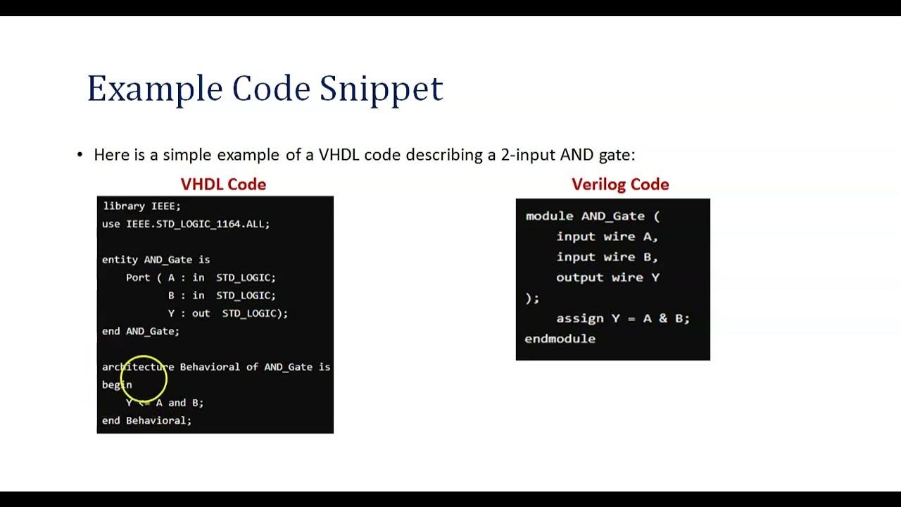
- 😀 Instead of physically building a circuit, Verilog code is written to describe its functionality and behavior.
- 😀 Modules in Verilog represent components of a digital circuit and can have input and output ports.
- 😀 Ports in Verilog are of two types: input (wires that bring data into modules) and output (wires that send data out).
- 😀 Data types in Verilog include 'wire' for connecting components and 'reg' for storing values that can change under conditions.
- 😀 Verilog allows three modeling styles: behavioral, dataflow, and structural modeling.
- 😀 In behavioral modeling, the functionality of the circuit is described with high-level logic (like if-else statements).
- 😀 Dataflow modeling focuses on how data moves through the circuit using logic expressions.
- 😀 A multiplexer (MUX) is a digital circuit that selects one of several inputs to forward to the output based on select lines.
- 😀 A 1-to-4 multiplexer has 4 inputs, 2 select lines, and 1 output. The output depends on the values of the select lines.
- 😀 In ZyLinks, Verilog code can be written for a MUX by defining inputs, outputs, and conditions based on the select lines, and testing it with a testbench.
Q & A
What is Verilog used for?
-Verilog is a hardware description language used to design digital circuits. It allows designers to describe circuits like processors and memory using code, instead of building physical circuits.
What is a module in Verilog?
-A module in Verilog is like a box that represents a part of a digital circuit. It contains inputs (signals that enter the module) and outputs (signals that leave the module), and multiple modules can be connected to form a complex system.
What are the two types of ports in Verilog?
-The two types of ports in Verilog are input ports (which bring data into the module) and output ports (which send data out of the module).
What is the difference between 'wire' and 'reg' in Verilog?
-'Wire' is used to represent signals that connect different parts of the circuit, while 'reg' is used for small storage spaces that hold values which can change based on certain conditions.
What are the three modeling styles in Verilog?
-The three modeling styles in Verilog are: behavioral modeling (describes what the circuit should do), data flow modeling (describes how data moves through the circuit), and structural modeling (describes how individual components like gates are connected).
What does a 4x1 multiplexer do?
-A 4x1 multiplexer selects one of four inputs and sends it to the output based on two control signals (S1 and S0). The output depends on the values of the select lines.
Can you explain the truth table for a 4x1 multiplexer?
-The truth table for a 4x1 multiplexer shows how the select lines (S1 and S0) determine which input is sent to the output. For example, when S1=0 and S0=0, the output is i0, when S1=0 and S0=1, the output is i1, and so on.
What are the steps to create a Verilog file in Xilinx?
-In Xilinx, first create a new project, then select 'Verilog Module'. After naming your module, define the inputs, outputs, and any necessary select lines. Finally, write the code for the circuit.
How do you simulate a Verilog design in Xilinx?
-To simulate a Verilog design in Xilinx, you need to create a testbench, which sets initial values for the inputs and tests the circuit's behavior. After running the simulation, you can observe the results and verify if the design works as expected.
What is a testbench in Verilog?
-A testbench is a Verilog code that simulates the behavior of a design. It provides the necessary input values and monitors the output. The testbench can be used to verify the functionality of the circuit before implementation.
Outlines

このセクションは有料ユーザー限定です。 アクセスするには、アップグレードをお願いします。
今すぐアップグレードMindmap

このセクションは有料ユーザー限定です。 アクセスするには、アップグレードをお願いします。
今すぐアップグレードKeywords

このセクションは有料ユーザー限定です。 アクセスするには、アップグレードをお願いします。
今すぐアップグレードHighlights

このセクションは有料ユーザー限定です。 アクセスするには、アップグレードをお願いします。
今すぐアップグレードTranscripts

このセクションは有料ユーザー限定です。 アクセスするには、アップグレードをお願いします。
今すぐアップグレード関連動画をさらに表示
Introduction to HDL (Hardware Description Language)

#1 Why verilog is a popular HDL | properties of verilog Language

Introduction

Introduction to HDL | What is HDL? | #1 | Verilog in English

Data Types in Verilog

Hardware Description Language Course Unit 8 (Midterms Week 8 Lesson) - Decoder Combinational Circuit
5.0 / 5 (0 votes)
