ORTHOGRAPHIC DRAWING EXAMPLE
Summary
TLDRThis clear, step-by-step engineering-drawing tutorial demonstrates how to produce orthographic (first-angle) projections — front, top, and left-side views — using basic tools (T-square and 45° triangle). The instructor lays out horizontal and vertical axes, establishes a miter/projection line and an invisible construction box, and transfers key measurements (notably 45 mm and repeated 15 mm segments) to build the front view. From there, vertical and horizontal projection lines create the top and side views. The lesson emphasizes light construction lines, converting them to visible outlines, and cleaning up guides to reveal the finished three-view autographic drawing.
Takeaways
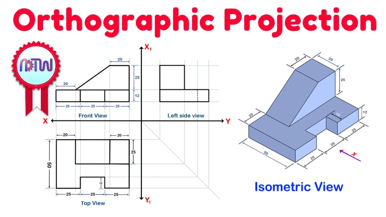
- 😀 Orthographic drawing involves creating three main views: front, top, and left side views of an object using projection techniques.
- 😀 The first step in orthographic drawing is to establish the horizontal (X-axis) and vertical (Y-axis) axes.
- 😀 Use a miter line (projection line) and a square to define the space for each quadrant in the drawing.
- 😀 For the front view, you need to measure and mark the object's width and height, using points to transfer the dimensions.
- 😀 The front view is created by determining the width and height based on the observer's line of sight and marking these dimensions on the axes.
- 😀 After drawing the front view, extend vertical and horizontal lines to prepare for the top and left side views.
- 😀 The top view is drawn by extending vertical lines down from the front view, marking corresponding dimensions, and drawing horizontal lines.
- 😀 The left side view is created by extending horizontal lines from the front view and projecting them to the left side view.
- 😀 The use of tools like a T-square and triangle is essential for accurate measurement and projection during the drawing process.
- 😀 After finishing the views, make sure to clean up any unnecessary lines and make the visible lines clear to finalize the drawing.
Q & A
What is orthographic drawing?
-Orthographic drawing is a method of projection used in technical drawing where an object is represented by three main views: the front view, top view, and left-side view. It provides a clear representation of an object's dimensions and shape from different angles.
What is the purpose of the miter line in orthographic projection?
-The miter line is used as a projection line to help align the different views of an object. It ensures that the three main views (front, top, and left-side) are placed accurately and in proportion to each other.
What role do the x and y axes play in setting up an orthographic drawing?
-The x and y axes represent the horizontal and vertical reference lines in the drawing. They help in positioning the different views and ensure accurate scaling and alignment of the dimensions in each quadrant.
How are the measurements transferred in an orthographic drawing?
-Measurements are transferred using a T-square and a triangle to ensure precision. These tools help in marking exact distances between points and ensuring that the lines are straight and correctly positioned in the drawing.
Why are light lines used in the setup of orthographic projections?
-Light lines are used during the setup phase to help guide the placement of dimensions and other features. They can be erased or adjusted later once the final visible lines are established.
How do you determine the height and width of an object in an orthographic drawing?
-The height and width of an object are determined by projecting lines from specific points of the object and measuring the distance between them. For example, the height is measured from the front view, while the width is determined by transferring horizontal distances.
What is the significance of the front view in an orthographic projection?
-The front view serves as the primary reference for setting up the other views. It shows the width and height of the object, and its dimensions are transferred to the top and left-side views.
How do you create the top view and left-side view from the front view?
-To create the top view and left-side view, you extend vertical and horizontal projection lines from the front view. This ensures the top and left-side views are aligned with the front view and maintain the correct dimensions.
What is the process for determining the left-side view in an orthographic drawing?
-The left-side view is created by projecting horizontal lines from the front and top views. These lines are extended to a miter line, and the intersections of these lines define the corners of the left-side view.
How do you finalize an orthographic drawing?
-To finalize the drawing, the visible lines are darkened, and all unnecessary light lines are erased. This results in a clear, legible representation of the object with accurate dimensions and projections.
Outlines

このセクションは有料ユーザー限定です。 アクセスするには、アップグレードをお願いします。
今すぐアップグレードMindmap

このセクションは有料ユーザー限定です。 アクセスするには、アップグレードをお願いします。
今すぐアップグレードKeywords

このセクションは有料ユーザー限定です。 アクセスするには、アップグレードをお願いします。
今すぐアップグレードHighlights

このセクションは有料ユーザー限定です。 アクセスするには、アップグレードをお願いします。
今すぐアップグレードTranscripts

このセクションは有料ユーザー限定です。 アクセスするには、アップグレードをお願いします。
今すぐアップグレード関連動画をさらに表示
Orthographic Projection from isometric view in Engineering drawing

Exercise 1.1 Orthographic Drawing
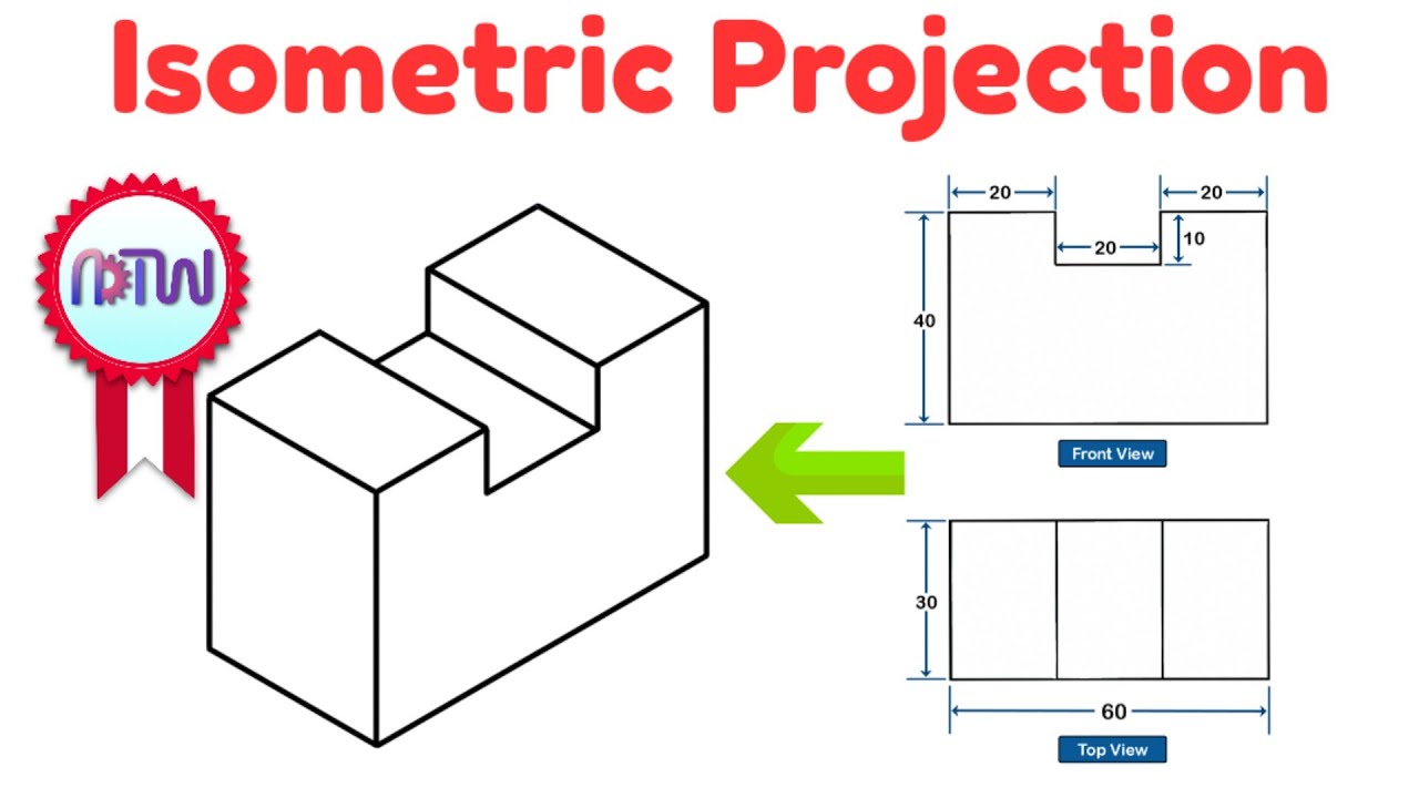
Isometric Projection in Engineering Drawing | isometric projection 3D from orthographic view
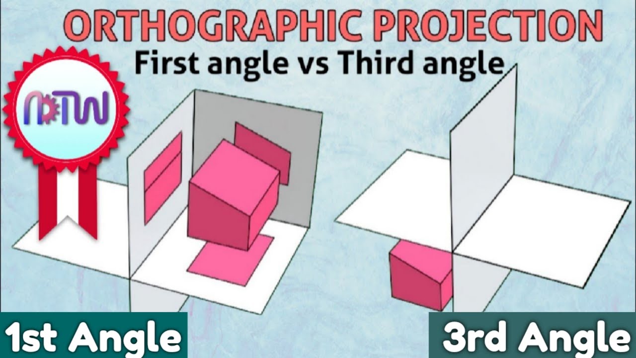
First angles vs Third angle method | Orthographic projections animation
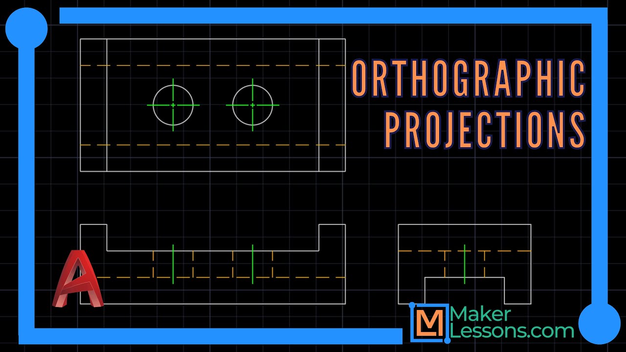
Learn AutoCAD: Simple 3 View Orthographic Projection - The Guide Block
Orthographic Projection Explained
5.0 / 5 (0 votes)
