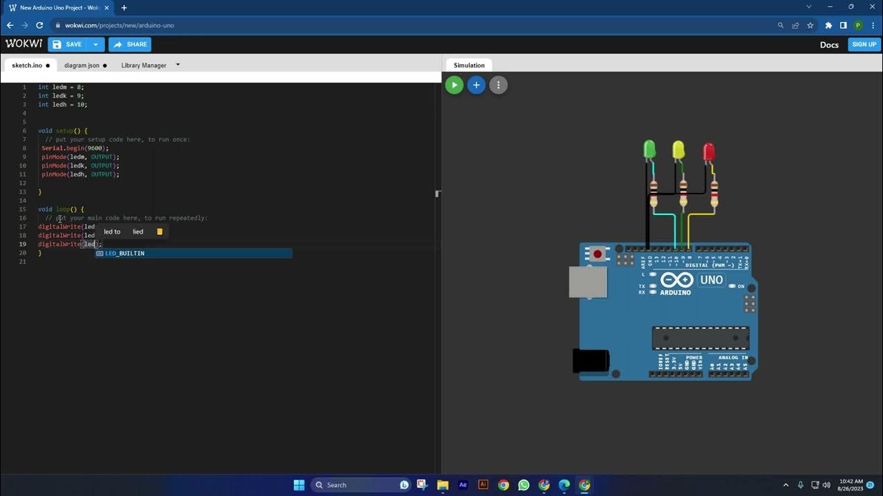
SIMULASI PROJECT ARDUINO DENGAN WOKWI: LAMPU MERAH
Summary
TLDRIn this tutorial, the speaker demonstrates how to simulate a traffic light project using LEDs and resistors. They provide a step-by-step guide, starting with the assembly of the components, including connecting the LEDs to the appropriate pins on an Arduino. The programming section outlines how to control the traffic lights, specifying the timing for each color—red, yellow, and green—while addressing minor errors in the setup. The video concludes with a successful demonstration of the traffic light sequence, reinforcing the learning process and encouraging viewers to experiment with similar projects.
Takeaways
- 👋 Introduction of the traffic light simulation project using LEDs and Arduino.
- 💡 Three LEDs are needed: red, yellow, and green, along with three resistors.
- 🔌 LEDs are arranged in a typical traffic light order: red on top, yellow in the middle, and green at the bottom.
- ⚙️ The anodes of the LEDs are connected to resistors, which are linked to specific Arduino pins (3 for red, 4 for yellow, 5 for green).
- 🌍 The cathodes of the LEDs are connected to the ground.
- 🎨 Colors of the LEDs are set to red, yellow, and green, with specific resistor values adjusted for each color.
- 📜 The Arduino code initializes the serial monitor and sets the pin modes for each LED.
- ⏳ The programmed sequence involves red light for 6 seconds, followed by yellow for 600 milliseconds, and green for 5 seconds.
- 🔄 Adjustments are made in the code to ensure the correct functioning of the lights during testing.
- ✅ The project concludes successfully, with the traffic light sequence working as intended.
Q & A
What is the main purpose of the project discussed in the transcript?
-The main purpose is to simulate a traffic light system using LEDs.
What materials are needed for the traffic light simulation?
-The materials needed include three LEDs, three resistors, and a way to connect them (like wires or a breadboard).
How are the LEDs arranged for the traffic light simulation?
-The LEDs are arranged to represent the red, yellow, and green lights of a traffic signal.
What is the function of the resistors in the circuit?
-The resistors are used to limit the current flowing through the LEDs, preventing them from burning out.
What programming language is used for the Arduino in this project?
-The programming language used for the Arduino is a variant of C/C++.
What is the initial state of the traffic light when the program starts?
-The initial state of the traffic light is the red light, which is programmed to turn on first.
How long does the red light stay on according to the program?
-The red light stays on for 6 seconds.
What changes are made to the yellow and green lights during the simulation?
-After the red light turns off, the yellow light turns on for a brief moment, followed by the green light for 5 seconds.
What troubleshooting step was taken when the green light did not turn on as expected?
-The pin assignments for the LEDs were checked and corrected to ensure the green light was properly connected.
What does the final message of the transcript convey?
-The final message thanks the audience and concludes the demonstration, indicating that the traffic light simulation is functioning correctly.
Outlines

このセクションは有料ユーザー限定です。 アクセスするには、アップグレードをお願いします。
今すぐアップグレードMindmap

このセクションは有料ユーザー限定です。 アクセスするには、アップグレードをお願いします。
今すぐアップグレードKeywords

このセクションは有料ユーザー限定です。 アクセスするには、アップグレードをお願いします。
今すぐアップグレードHighlights

このセクションは有料ユーザー限定です。 アクセスするには、アップグレードをお願いします。
今すぐアップグレードTranscripts

このセクションは有料ユーザー限定です。 アクセスするには、アップグレードをお願いします。
今すぐアップグレード関連動画をさらに表示

Making Traffic Lights with Arduino Uno - Beginner Level (algorithm, coding, circuit design)

Best Science Project | Smart Street Project | Inspire Award Project | Smart City Project

New Science Project, Free Energy Based Science Project, Automatic Street Light Project #science

Cara Membuat Rangkaian Sederhana Sensor Air Hujan

Belajar Bahasa Pemrograman Arduino dengan WOKWI Simulasi Traffic Light Lampu Lalu Lintas

KENAPA TIDAK DARI DULU TAU CARA INI ‼️ Modifikasi Stop Kontak Jadi Super Canggih
5.0 / 5 (0 votes)
