Computer Basics: Hardware
Summary
TLDRThis video script offers a comprehensive tutorial on disassembling and reassembling a standard PC. It guides viewers through the process of opening the computer case, removing components such as the power supply, hard drive, and CD ROM, and then taking apart the motherboard. The script meticulously explains the removal and reinstallation of each part, including the processor and memory. It also covers the reconnection of cables, the importance of alignment, and the correct seating of components to ensure the system functions properly once reassembled.
Takeaways
- 🛠️ To access the inside of a computer, lay it down, and remove the case by unscrewing thumb screws and sliding the back off.
- 🔌 The power supply is crucial as it provides power to the system board and components via connectors.
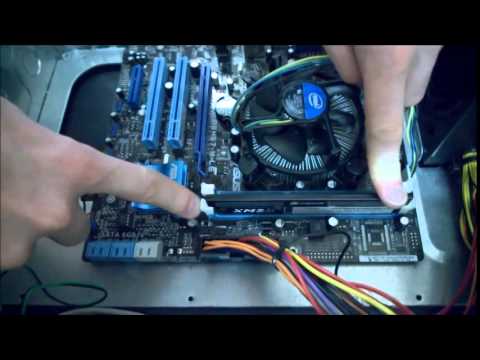
- 💻 The motherboard is the central board that connects all the computer components, including the processor, hard drive, and CD ROM.
- 🖥️ SATA cables are used to connect storage devices like hard drives and CD ROMs to the motherboard and can be detached by squeezing a release pin.
- 🔄 Before removing components, ensure all power cables are disconnected to avoid damage.
- 🔩 To remove the power supply, unscrew it from the back and slide it out, being careful not to lose any screws.
- 💾 Hard drives can be removed by sliding them out after removing the screws that hold them in place.
- 📀 The CD ROM drive is also removed by unscrewing and sliding it out from the front of the computer.
- 🔧 Removing the system board requires disconnecting all cables and components attached to it, including memory and PCI cards.
- 🔠 The motherboard has various ports and connectors for power, data, and peripherals, which need to be matched correctly when reconnecting.
Q & A
What are the steps to open the case of a standard PC?
-To open a standard PC case, locate the thumb screws on the back, unscrew them, slide the back panel off, and then lift it up to remove the case.
How do you disconnect the power supply from the motherboard?
-Disconnect the power supply by squeezing the pin on the power connectors and pulling them out of the motherboard.
What are the SATA cables used for in a computer?
-SATA cables are used to connect storage devices like hard drives and CD ROMs to the motherboard.
How do you remove the power supply unit from a computer?
-To remove the power supply unit, first, remove the four screws on the back with a Phillips screwdriver, then slide the power supply forward and lift it out.
What is the purpose of the processor fan and heatsink in a computer?
-The processor fan and heatsink are used to cool down the microprocessor, preventing overheating and ensuring the system runs smoothly.
How do you remove the hard drive from a computer?
-Remove the screws on either side of the hard drive, slide it forward, and then pull it out.
What is the correct way to remove a PCI card from a motherboard?
-To remove a PCI card, first, unscrew any screws holding it in place, then push down on the lever to release the card and pull it out.
Why is it important to match the notches when installing the processor?
-Matching the notches ensures that the processor is correctly aligned with the socket on the motherboard, preventing damage and ensuring proper function.
What is the purpose of thermal paste when installing a processor?
-Thermal paste is used between the processor and the heatsink to improve heat transfer, keeping the processor cool during operation.
How do you reconnect all the cables to the motherboard after a clean install?
-Reconnect the cables by matching the color-coded connectors to their corresponding ports on the motherboard, ensuring each cable is plugged in correctly and securely.
What is the role of the front panel connectors on a motherboard?
-The front panel connectors on a motherboard are used to connect the power button, USB ports, audio jacks, and other front-panel components to the system.
Outlines
🛠️ Disassembling a Standard PC
The paragraph provides a step-by-step guide on how to open a standard PC case and access its internal components. It begins with removing the screws at the back and sliding off the case. The internal components such as the power supply, processor fan, hard drive, CD ROM, and motherboard are identified. The guide then explains how to disconnect the SATA and power cables from the hard drive and CD ROM by squeezing the release pins. It also covers the removal of the power supply unit by unscrewing it from the back and lifting it out. The process of removing the hard drive and CD ROM drive is also detailed, including the removal of screws and sliding the drives out.
🔩 Removing Components from the Motherboard
This section details the process of removing the system board from the computer case. It starts with disconnecting all cables and components attached to the board, such as memory and PCI cards. The guide explains how to remove the memory by releasing the tabs on both sides and sliding the memory out. For PCI cards, it mentions the need to remove a cover and unscrew the card before pulling it out. The paragraph also covers disconnecting front panel cables like USB, audio, and power button connectors from the system board. Finally, it describes how to remove the motherboard by unscrewing it and sliding it out of the case.
🔧 Understanding and Replacing Processor
The paragraph focuses on the components of the system board and the process of replacing the processor. It describes various connectors and ports on the motherboard, such as power, IDE, floppy drive, SATA, PCI, and audio ports. The guide then explains how to remove the processor from the heatsink using a screwdriver and how to ensure proper alignment when reinserting the processor into the socket. It emphasizes the importance of applying thermal paste for effective cooling. The paragraph concludes with a discussion on the different components found on a motherboard, including capacitors, resistors, and chipset heatsinks.
🔠 Reassembling the Computer System
This section guides through the process of reassembling the computer system. It starts with placing the motherboard into the case and aligning it with the ports on the back. The guide advises on securing the motherboard with screws and ensuring all corners are anchored to prevent short circuits. It then covers the reinstallation of components like the CD ROM and hard drive, including connecting the necessary SATA and power cables. The guide also explains how to reinstall the power supply, making sure it is securely fastened. The paragraph concludes with reconnecting all the front panel cables, such as audio, USB, and power LEDs, and installing the PCI card and front panel.
🔌 Completing the Reassembly and Testing
The final paragraph wraps up the reassembly process by connecting the last of the front panel cables, including the power LED, hard drive LED, and reset switch. It also covers the installation of the PCI card and the reattachment of the computer case. The guide ensures that all components are securely in place and that the case is properly closed. The paragraph ends with the computer being restored to its normal state, ready for testing and use.
Mindmap
Keywords
💡PC
💡Connectors
💡Power Supply
💡Motherboard
💡SATA Cables
💡Processor
💡Memory
💡PCI Express
💡Front Panel
💡System Board
💡Thermal Paste
Highlights
Introduction to disassembling a standard PC with no specific markings.
Procedure to open the computer case by removing thumb screws and sliding back the panel.
Overview of the internal components of a computer, including the power supply and motherboard.
Explanation of the processor fan and heatsink's function over the microprocessor.
Identification and discussion of the hard drive, CD ROM, and SATA cables.
Demonstration of disconnecting SATA cables from the hard drive by squeezing the pin.
Description of the power supply's role in providing power to the system board and components.
Instructions on disconnecting power cables from the system board and case fans.
Removal of the power supply from the computer case after unscrewing.
Steps to remove the hard drive by sliding it forward after removing screws.
Process of removing the CD ROM drive by unscrewing and pushing it out from the back.
Guidance on disconnecting components and cables attached to the system board.
Technique for removing the memory stick from the motherboard by releasing the tabs.
Method to remove a PCI card by unscrewing and pulling it out from the motherboard.
Discussion on the various connectors and ports on the front panel of the system board.
Procedure to remove the system board by unscrewing and sliding it out of the case.
Description of the components on the system board, including power, IDE, SATA, PCI, and USB ports.
Explanation of the processor socket and how to correctly align and insert the processor.
Instructions on reassembling the computer by reversing the disassembly steps.
Importance of applying thermal paste when reattaching the processor to the heatsink.
Final steps to close the computer case and ensure all components are securely in place.
Transcripts
this is a standard PC uh no markings uh
you can buy this at any store any
Computer Outlet
um to get into the computer you look at
the back make sure that all your
connectors when you lay the computer
down all the connectors are on the
bottom um these are thumb
screws you unscrew them
put them off to the side and you slide
back and then lift up just takes the
case
off now this is the inside of a
computer you have a power
supply these connectors come off the
power supply Supply power to everything
on the system board and on the
components this is a processor fan heat
sink which is over the microprocessor
processor there's several components
that are on here that we'll talk about
later you have your hard drive you have
your CD
ROM and this is this component down here
is called your
motherboard we're going to take this
apart the blue cables that you see here
are called SATA cables sat a SATA cables
there's a pin on the top of one of these
you squeeze and pull see this pin here
what you do is you squeeze that pin down
and you pull out and it comes off of the
hard drive and I'm going to take the
power which has the same type of
connector only just a little bit longer
we going to do the same thing up top
squeeze and
pull same thing with the power squeeze
and pull the power is supplied through
the power supply the S cable is supplied
through the system
board this these cables here these SATA
cables are connected to SATA ports that
are on the system board
again you squeeze and you
pull set these off to the side as
well we're going to start disconnecting
power to everything this power cord
right here connects to a case
fan they simply just
unplug this power connector connect
conect all the power to the system
board
squeeze and pull directly out it's got
this little clip it Clips onto the side
of the system
board again another case fan unplugged
power and you have a four-prong power
connector down
here supplies more power to the
board it also has a little squeeze pin
and it pulls right out
now your power supply is completely
disconnected from your system
board now we're going to remove the
power
supply okay to remove the power supply
there are four screws on the back
side get a Philip
screwdriver make sure you don't lose
your
screws
[Applause]
once you finish taking out all four
screws power supply should just fall
slide forward tilt back towards the
board lift straight
out that is a removal of a power supply
now let's remove the hard
drive normally there are two screws hold
power supply in on either side top and
bottom let's remove the hard drive
screws and remove the hard
drive slides
forward and your hard drive has been
removed if you have screws on the on the
other side on the opposite side stand
the computer back up
remove the screws on the on what we call
the bottom side remove your thumb screws
Slide the tray open up that portion of
your computer these two screws will
release the CD ROM
drive turn it back
around
two screws on this
side once you've removed the screws from
the CD ROM push from the back out
forward and your CD ROM slides forward
now to remove the system board you can
first have to remove each one of the
components that are tied to it cables
PCI connectors or P PCI Express whatever
external cards or what they call add-on
cards you'd have to remove those this is
considered memory doesn't necessarily
have to be removed when you're Mo
removing the motherboard but you can to
remove the memory there's a tab on
either side you pull the tab out pull
this tab on the other side
out and the memory
slides right out there's your memory
stick now we're going to remove this PCI
card to do that you'll see the screws
inside here it's hard to get to there's
a cover on the back side that we have to
remove first this is not normal on on
all comp on all computers some of the uh
the big box computers do not have these
most custom cases
will remove your case it exposes all
your
screws you find which one has the the
silver tab that usually indicates a an
add-on card unscrew it
go back into the
case grab both corners and pull straight
out this will take your card your PCI
card off of the system
board now most of the cables that you
see here come from the front
panel the front panel has a card reader
it's got USB ports audio headphone jack
it's got a power button a power LED or
power light and it's got indicators for
your hard drive and another lights on
the
front so what we want to do is
disconnect those cables from your system
board real simply don't you don't don't
pull too hard just grab firmly and ease
them out just pull lightly and they'll
all unplug and notice how they fan
apart this is your USB cables do the
same thing
grab lightly and
pull these do not fan apart and it has
the word USB or has the the uh letters
USB on them this will tell you these are
for the USB ports and the card reader
for up front then this cable again pull
from here it tells you that it's an
audio port came from
here and it'll tell you on the system
board where it says
audio now let's let's remove the
motherboard to remove
the the system board there's there
screws that hold it on these screws are
are
indicated by little
circles throughout the system board and
that holds it in place so it won't it
can't move and once we remove those
screws the system board should slide
towards the front of the case and pull
straight out
okay I'm using a lightly mag magnetic
tipped screwdriver to kind of help some
people don't uh don't necessarily think
it should be used and if that's the case
if you don't feel comfortable with that
then then don't use them I'm sure
whenever you're putting these screws
back in that you don't uh you don't
overtighten them they just need to be
tightened up enough to where it it holds
steady motherboard should lift straight
up now that you have your system board
out you can replace your processor this
is the easiest thing way to do it I like
to put the the processor and the heat
sink on before I set your set my
motherboard back in my box or or replace
it the reason being is it allowed me one
to handle the the device a little easier
and two I'm not confined in space so
what I want to do is on on every heat
sink you're going to find a fan that fan
usually has a power cordin it's usually
plugged
in to a power connector and it'll tell
you on the on the Sy boards where a CPU
fan should be plugged into this is on an
anti-static bag so that you don't uh you
don't any static electricity to the
system board unplug your power
again it you don't have to yank on them
just slightly pull them out um there's a
screw inside of each one of these that
you can remove the fan some people
remove the fan or you can just remove it
by this take that lever and you lift it
up get you a flathead
screwdriver push
down and it releases it on this
side once it releases from this
side you
can release it from that side and your
whole
processor should lift right off of
there now this processor is mounted it's
not mounted but it's stuck to the heat
sink because of the heat sink paste take
your screwdriver and lightly turn
it and that should break it loose and
that is your
processor this is the arm that it comes
off of locks it into place on each
processor you have a row of pins they
have a pattern inside you'll notice that
there's four holes missing there's also
four holes on the system board itself on
the processor socket when you match up
your triangles you set it back down into
place that pattern will match up you
don't want to force it it should drop
right into place if you match up your
triangles you lock it back
down and you're
finished so let's talk about the
components on the system board um this
is your power main power from your power
supply this is a IDE connector for the
older IDE hard drives or or CD ROM
this is a floppy Drive connector just in
case you have a floppy Drive which they
don't really make hardly anymore these
are SATA connectors SATA stands for
Serial ATA if you'll notice inside they
they're very distinctive uh your SATA
zero is your highest port it's your main
Port where your where your uh hard drive
would plug to and then you have your
SATA one two three on the other side for
any others you have PCI slots you have a
video port
uh the only thing that fits in this port
would be a video card PCI Express video
card you also have a PCI Express 2 uh
which is another video card these
pinouts up here uh is where you would
plug your front panel uh for your power
switch and your your front speaker the
LED lights this is your USB port you'll
notice what it says up here these are
both your USB connectors for the front
this is a Communications port in case
you have a uh Communications card in the
front you also have on the back you have
audio ports which is your your speaker
microphone your headphone Jacks you have
an Ethernet connector for your network
you have two USB ports here uh four more
on this side you have a DVI port you
have an a VGA port both of these are
video you have if you notice this one's
green and purple this this is a PS2 Port
you can plug either a mouse or a
keyboard and then you have two more USB
ports on the front side your memory
socket sockets you have two uh DDR
memory sockets right here this processor
is an AMD processor you can tell cuz it
says am3 or am2 plus this is your
processor socket these are the mounts
your heat sink this is your gigabyte
motherboard this is a
chipset uh heat sink it keeps your your
CH chipset cold uh are cool um then you
have variety of capacitors and um and
resists and different little chips on
the board that will help you this is
called a Coss
battery you have your audio
port uh that's basic the basic
components of a system board and and all
system boards uh are different some of
them won't have a floppy um uh um Port
some some of them will not have an IDE
port anymore everything's going to sated
drives you may not have a PCI I mean a
PCI Express connector anymore you may
just have the PCI
2 uh you may not even have any PCI
connectors this is your four port power
connector uh which which supplies power
to the processor and all the ports in
the back here uh this power connector
supplies ports to power to everything
else and that's basically the components
you have uh you have fans to plug in
here on either side this is right here
for spit if is is um surround sound IO
right here another audio port and that
should that's your basic
components now that we have everything
apart we're going to put everything back
together we have our processor back in
and it's locked down um the good thing
to remember is the paste that you see on
here anytime you're putting it putting a
a processor back on you want to add uh
some type of thermal paste back on
between the processor and the and the
heat sink itself to kind of keep that
that section cool so what we're going to
do is we're going to turn this all the
way back around just like we had it and
we're going to set it back in
place we're going to turn it and we're
going to make sure that it's locked down
on this side
here so when we turn it back the other
side this portion we have to push down
on just a little bit where it locks into
place now that we've got this pushed
down on both sides we're going to lock
the lever in
place and that keeps this from
moving now we take our power connector
four port power connector it's got the
little slide so it tells you which way
it's supposed to go and it slides all
the way down to the bottom till you hear
it
connect now that we have this in place
we can add our memory
back as well the memory can go in on the
outside just as just as easy as it can
on the inside so they want to line up
the grooves with the grooves that are in
the in the system boards
themselves so you want to make sure that
the grooves match up before you insert
it want to make sure our Tabs are
open on both sides there's a rail that
it goes
into here and
here and then you want to push down on
both sides firmly until you hear it
click if you have two you can put it on
either one of them if you have an
additional memory you can add that to it
as well this just has a single stick of
memory in it and we'll get into that
further in another video what's what
type of memory and what type of slot so
now we're ready to put this back into
the system board and right back into the
uh into the computer so we take our case
like we had before it's empty and we
want to add the system board back in so
we're going to lay it back down we're
going to put the motherboard the the
motherboard back in notice on the
back how you got your
holes aligned where each one of the
components go and it tells you where the
keyboard or Mouse and it tells you all
the other things and we want to align
the back of
these with the ports that are on the
back of this now anytime you buy a
system board this plate pops in and pops
out so it doesn't matter if you have a
generic case and a generic motherboard
you can pop this portion of the case out
and put the one that comes with your new
board in so it matches up so let's set
our case back
down you want to take your system board
make sure that your components are
facing the back you want to go in and an
angle moving all your cables out of the
way you want to make sure that it
matches
up with all your components in the back
[Music]
make sure that nothing is poked out make
sure that you're all in the right
place and you want to make sure that you
can see your screw
holes and that they're matched up as
well again when you're putting your
screws back in you don't have to to Bear
down on them just make sure that they're
snug make sure that the system board
will not
move it doesn't jump
because as you plug components into it
you don't want it to
shift the ones back here by the by the
back of the system board are the ones
that are a little more tough to get to
because of the lip on here just you can
use a SC shorter screwdriver or an
actual longer screwdriver just to get
the uh get your your screwdriver away
from the edge
there the main concern with the screws
is you want to make sure that all four
corners Corners are tied down or
anchored you can short a system board
out without with the wrong screw or with
not having a screw uh added could uh
could add a short to the system board
which will cause your system board not
to power
up so make sure that you don't have
anything except for the brass inserts
underneath where you're screwing these
two and once you have your brass inserts
everything else should fall right into
place okay we're going to add the CD ROM
back to your uh back to your
system you want to make sure your sated
connectors the same ones that are on the
board system born the SATA and then your
power say so you want to slide it in
from the front until the front piece
matches with the front of your case and
your screw holes are lined up you want
to take your screws you want to make
sure that they're snug you don't want to
you don't want to have
to bear down on them too hard you just
want to be able to get them
into place to where it holds the CD ROM
in
place now that you're CD ROM's in place
we're going to add the hard drive back
your SATA connectors that are on here
this is power if you if you have ID
power and you don't have SATA power this
hard drive has both power connectors so
you can add a power connector similar to
this from your power supply if you need
to or just use regular SATA power I'm
going to add this back in what we want
to do is we want to find our
ledge where we want it we're going to
slide it back
in notice our screw holes are lined up
into the
slots we can slide it all the way as far
back as we
want or we can bring it as far out as we
need
to the adjustment is purely up to you
and the space that you
have take your
screw
line it
up doesn't slide either
way now that these two components are
back in we're going to add the power
supply we will add a PCI card uh all the
other components are in but I want to
add the power supply now to show you how
everything plugs back into
place power supply will go upside down
just depends on the on the back
angle you want to go in at an angle up
turn it straight slide it forward you
want to match up your holes your screw
Hol like most power supplies there's a
ledge on top
underneath that'll help you hold it in
place so when you're ready to screw it
in you line up your screw holes you
screw your power supply back in and this
one you want to make a little more snug
than the rest of them this has this is
all your power here so you want to make
sure that it doesn't uh it doesn't come
loose now your power supply is in snug
it's not going anywhere now let's plug
in our 24 pin power
connector there 24
pins on your system board it has 24 pins
your plug your squeeze um pin is on this
side right here that locks and unlocks
them and there's a there's a ledge on
the edge of your power connector there
so you just line up your
pins with the holes that are there and
push until you hear a snap and it's
locked into place your four pin power
connector again your clip there's your
power connector there there's your clip
there's a ledge on the a lip on the edge
you line up the holes it only goes one
way it won't go the other way and push
until you hear it until that clip
clicks now we want to add add power to
the rest of our system this is power
this is a power plug that we can add for
the CD
ROM add that power
back again it only goes One
Way power for the power for the for the
hard
drive power is
there
now your SATA plugs SATA plug for the CD
ROM SATA plug for the hard drive exactly
same
setup the difference is this one's kind
of a 90° angle which allows it to uh to
be put in this way the the P the the
system board I mean the hard drive
doesn't need it cuz you got more room
over here they do this in tight spots uh
where you can get to them a little
easier so our hard drive zero sata2 0 is
going to plug to the to the system board
notice the L shape on this one as
well there's the there's the connector
for it we going to push until we click
here it
click take this side again with the L
shape sideways L and we're going to plug
it to the hard
drive push until you hear it
click just like that and we're going to
do the same thing for the CD
ROM does it matter what port the CD ROM
goes to there's SATA zero then SATA 1
SATA 2 and sata 3 does not matter choose
SATA one the next drivein
line you feed your cable up and you plug
it against your CD ROM you want to try
to keep your cables as neatly as
possible that way you're they're not
running into your fans and you you're
not cumbersome and then you have your
other cables that plug into your system
board as well so let's start off with
the audio audio cable and if you
remember the audio plug was back here
notice the pins on this have a certain
pin out there's there's five pins then
there's three and number four is missing
and we have five on the other one as
well the same pin out as on
this we have five pins we have three one
missing and then
five so we want to make sure we line
those up
correctly and push all the way
down now we want to do the
USB and the card reader notice the pin
outs are a little different on this
one you have five then you have four and
then the last one's missing on that side
so you find your pen out the way you
want it on
here slide it into
place do the same on this one slide it
into
place this is a power connector for a
fan on on all power
supplies your power connector main power
is going to go red then black then
yellow anytime you plug in to another
Power connector you want to match up the
colors and they snap right into
place this one doesn't have red and
black so we want to find out we want to
make sure that power is the red is going
to this power here so we want to go
ahead and Slot it in place as well
this is a power LED positive and
negative this is our hard drive
LED and this is our reset
switch so those plug to this port right
here you're going to have to find where
the color codes on this but if you'll
notice it tells you which where each one
of them plug
in so if it's closest to this it's on
this side if it's on farthest away it's
on the opposite
side now that we've uh we've got our
cables plugged in connectors for the
front panel Let's uh let's install the
PCI card with the PCI card you uh make
sure it's lined up in your empty slot
and then you push down here and it snaps
into place and your screw you got to add
your screw back to it put your case back
on last thing we're going to do is put
our panel back
on make sure that the uh grooves line up
with where they go slides right back on
put your thumb screws back in and you
are back to
[Music]
normal
関連動画をさらに表示
Saylor.org BUS206: Dr. Davd Bourgeois' "The Hardware Component"
Parts of a Motherboard and Their Function - Part 2 Back Panel Connectors & Ports
Computer System Hardware
Mengenal komponen-komponen dalam Motherboard Komputer beserta penjelasan fungsinya
What does what in your computer? Computer parts Explained
What Is Computer Hardware ? | Beginners Guide To Computer Hardware.
5.0 / 5 (0 votes)