Pick and Place Robotic Arm programming in PLC Programming Tutorials for Beginners
Summary
TLDRThis tutorial covers the creation of a ladder logic program for a pick-and-place robotic arm using PLC programming. The system picks up a box, moves it from left to right, and places it onto a conveyor using pneumatic cylinders and sensors. The program involves controlling the movement of the cylinders, activating the vacuum to grip the box, and managing the motor outputs to move the system. The tutorial also demonstrates the practical application of the logic and the setup of inputs and outputs, with a brief product review of a signal generator tool. A step-by-step approach makes it accessible for beginners and experts alike.
Takeaways
- 😀 The tutorial covers PLC programming for a pick-and-place system with a pneumatic cylinder and vacuum cup to move boxes.
- 😀 The system involves sensors to detect box presence and positions, as well as motors for system movement between conveyors.
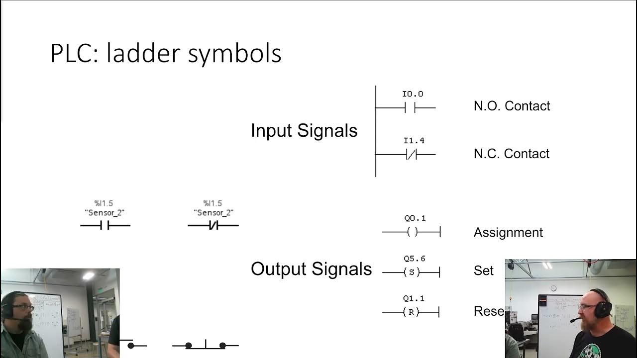
- 😀 The ladder logic is explained in detail, outlining the process of programming the PLC to control the system's actions.
- 😀 Box presence is detected by a sensor (I0.0), which triggers the pickup process when a box is detected.
- 😀 The pickup cylinder (Q0.1) moves down to grab the box when the vacuum cup (Q0.0) is activated.
- 😀 The system is moved to the right side using a three-phase motor controlled by output Q0.2, with position confirmation by sensors (I0.3, I0.4).
- 😀 The box is dropped onto the right-side conveyor when the cylinder reaches the down limit (I0.2), and the vacuum is turned off.
- 😀 After dropping the box, the system returns to the left side home position, and the logic is used to reverse the motor (Q0.3).
- 😀 The vacuum cup (Q0.0) is reset when the box is dropped, releasing it onto the right conveyor.
- 😀 The video also introduces a signal generator tool, useful for beginners and experts in troubleshooting and simulating analog signals.
Q & A
What is the primary purpose of this tutorial?
-The primary purpose of this tutorial is to teach how to create ladder logic for a small pick-and-place robotic system, which picks up boxes from one conveyor and places them onto another.
What is the function of the box sensor in this system?
-The box sensor (I 0.0) detects the presence of a box on the conveyor, which triggers the system to begin its operation.
How does the pickup pneumatic cylinder function in this system?
-The pickup pneumatic cylinder (Q 0.1) moves up and down to pick up and place the box. It is controlled by the PLC output, moving the cylinder to grab and release the box as needed.
What is the role of the vacuum cup in the pick-and-place process?
-The vacuum cup (Q 0.0) is attached to the pickup cylinder and creates suction to hold the box during the lifting process. It is turned on when the cylinder reaches the down position to grab the box.
How are the cylinder positions monitored in the system?
-The cylinder positions are monitored using limit sensors (I 0.1 for the up limit and I 0.2 for the down limit), which confirm whether the cylinder is in the correct position before continuing the process.
What role do the left and right limit sensors play in the system?
-The left (I 0.3) and right (I 0.4) limit sensors confirm the position of the entire system, ensuring that it is properly aligned before and after moving the setup from one side to the other.
How is the system moved between the left and right sides?
-The system is moved by a three-phase motor controlled by the PLC outputs (Q 0.2 for moving right and Q 0.3 for moving left). The motor is energized when the appropriate conditions are met, such as confirming the position through limit sensors.
What happens when the system reaches the right side with the box?
-When the system reaches the right side, the pickup cylinder (Q 0.1) moves down to release the box onto the right side conveyor. The vacuum cup (Q 0.0) is turned off to release the box.
How does the program handle the return of the system to the left side?
-The program energizes the reverse motor (Q 0.3) to move the system back to the left side after dropping the box. The movement is confirmed when the system reaches the left limit sensor (I 0.3).
What other equipment is mentioned in the video and what is its purpose?
-The video mentions the SG004A signal generator tool, which can simulate various electrical signals (e.g., 4-20 mA, RTD, thermocouple). It is used for troubleshooting and learning about analog signals in control systems.
Outlines

Cette section est réservée aux utilisateurs payants. Améliorez votre compte pour accéder à cette section.
Améliorer maintenantMindmap

Cette section est réservée aux utilisateurs payants. Améliorez votre compte pour accéder à cette section.
Améliorer maintenantKeywords

Cette section est réservée aux utilisateurs payants. Améliorez votre compte pour accéder à cette section.
Améliorer maintenantHighlights

Cette section est réservée aux utilisateurs payants. Améliorez votre compte pour accéder à cette section.
Améliorer maintenantTranscripts

Cette section est réservée aux utilisateurs payants. Améliorez votre compte pour accéder à cette section.
Améliorer maintenantVoir Plus de Vidéos Connexes

Example PLC: EATON EASY Intelligent Relay (Full Lecture)
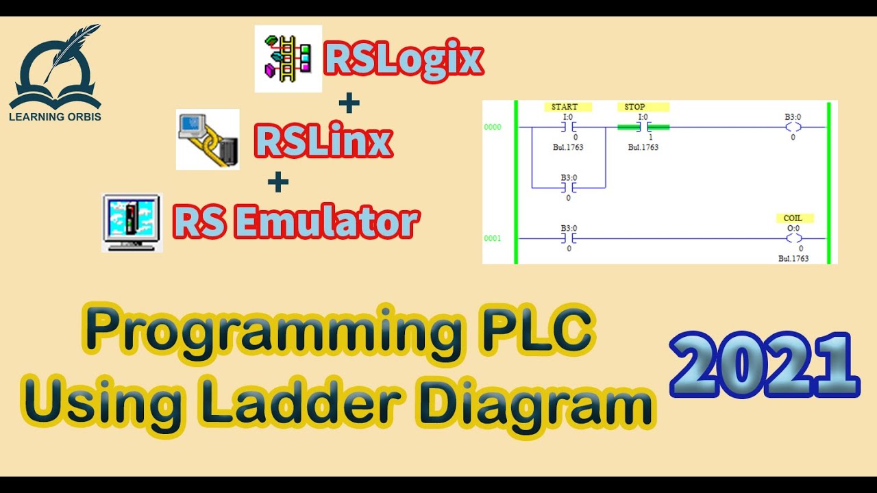
How to Program PLC Using Ladder Diagram | RSLogix

Want to Master PLC Programming? Watch This Now
SysAp 7 1 Ladder Logic
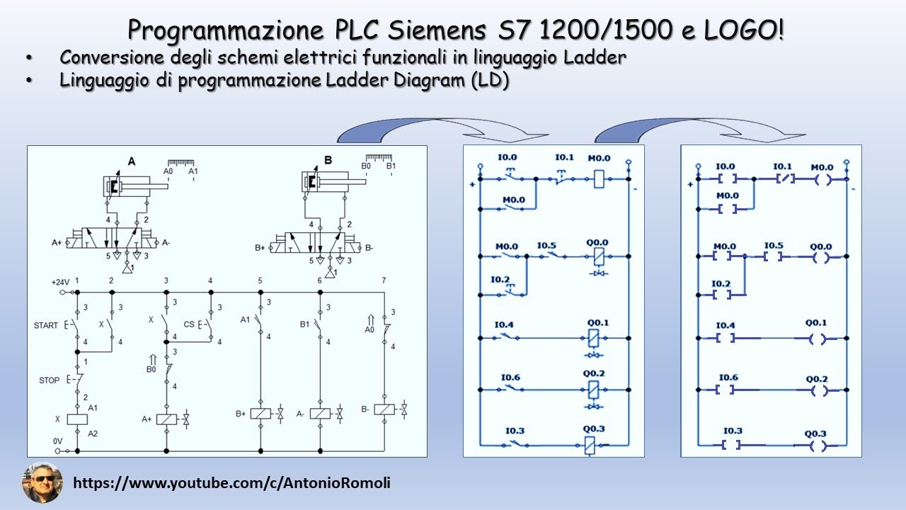
PLC: convertire lo schema elettrico funzionale in linguaggio di programmazione Ladder (Video 1.1)

Ladder Logic Diagrams for PLCs | Industrial Automation
5.0 / 5 (0 votes)
