Pengukuran Besaran Listrik - Oscilloscope
Summary
TLDRThis video tutorial provides a comprehensive guide on how to use an oscilloscope for measuring voltage and frequency in an electronic circuit. The presenter explains the setup, calibration, and operation of the oscilloscope, including how to connect probes and adjust settings for accurate readings. A practical experiment is demonstrated with a simple AC circuit using a diode for rectification, allowing viewers to compare AC and DC signals. Key concepts such as peak voltage, RMS values, and frequency measurement are covered, making this a valuable learning resource for electronics enthusiasts.
Takeaways
- 😀 The script introduces the basic use of an oscilloscope for measuring voltage and frequency in an electronic circuit.
- 😀 The oscilloscope has two channels (Channel 1 and Channel 2) for displaying signals, and the probe is connected to Channel 2 for this demonstration.
- 😀 The position and scale controls on the oscilloscope allow users to adjust the vertical and horizontal axes to properly display the signal.
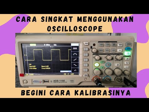
- 😀 The script emphasizes calibrating the oscilloscope before starting measurements, setting the vertical scale to represent 1 volt per box and the horizontal scale to represent frequency.
- 😀 The process for calibration involves connecting the probe and adjusting the settings for a clean and readable signal.
- 😀 The oscilloscope can be used to measure both the peak-to-peak voltage and the frequency of a signal, as seen during calibration.
- 😀 The demonstration includes measuring an AC signal before and after it passes through a diode to show the difference between an AC and DC signal.
- 😀 The peak voltage measurement on the oscilloscope is 9.2V, and the RMS value is 3.26V for the original AC signal.
- 😀 After the signal is rectified by the diode, the oscilloscope shows a DC signal with a peak voltage of around 4V and an RMS value of 1.43V.
- 😀 The frequency of the signal is measured at 50Hz, consistent before and after the rectification process.
- 😀 The oscilloscope's digital features allow immediate reading of both peak voltage and frequency, enhancing measurement efficiency.
Q & A
What is the main objective of the practical session described in the transcript?
-The main objective of the practical session is to demonstrate how to use an oscilloscope to measure voltage and frequency from an input circuit, and to understand the output displayed on the oscilloscope.
How many channels are available on the oscilloscope, and which one is used in the demonstration?
-The oscilloscope has two channels available, Channel 1 and Channel 2. In the demonstration, Channel 2 is used.
What is the purpose of the vertical and horizontal position adjustments on the oscilloscope?
-The vertical position adjustment is used to change the positioning of the signal along the vertical axis, while the horizontal position adjustment moves the signal along the horizontal axis, making it easier to read and measure the signal.
What does the scale adjustment on the oscilloscope represent, and how is it used?
-The scale adjustment controls the representation of voltage and time on the oscilloscope. The vertical scale (volts per division) is used to adjust the voltage per grid, while the horizontal scale (seconds per division) adjusts the time per grid, allowing for the measurement of frequency.
What is the purpose of calibrating the oscilloscope, and how is it done?
-Calibration is done to ensure accurate readings on the oscilloscope. In the demonstration, the calibration process involves adjusting the scale to match a known reference signal, with each grid unit representing a specific voltage value.
What type of signal is initially measured before the diode in the circuit, and what does its waveform look like on the oscilloscope?
-The signal measured before the diode is an AC signal. Its waveform on the oscilloscope appears as a sinusoidal wave, which is characteristic of alternating current.
How does the signal change after passing through the diode in the circuit?
-After passing through the diode, the AC signal is rectified, resulting in a DC signal. This change is reflected on the oscilloscope, showing a waveform that represents a pulsating DC signal.
What is the significance of the 'peak-to-peak' voltage measurement on the oscilloscope?
-The peak-to-peak voltage measurement indicates the full voltage swing from the highest point (peak) to the lowest point (trough) of the waveform. It helps in determining the overall voltage variation of the signal.
What is the significance of the RMS (Root Mean Square) voltage reading on the oscilloscope?
-The RMS voltage represents the effective value of the waveform, which is equivalent to the DC voltage that would produce the same power dissipation in a resistive load. It is important for understanding the average power of the signal.
How does the frequency of the signal appear on the oscilloscope, and how is it measured?
-The frequency of the signal is visible on the oscilloscope as the number of cycles the waveform completes in a given time period. In the demonstration, the frequency is read as 50 Hz, which is the number of complete cycles per second.
Outlines

Cette section est réservée aux utilisateurs payants. Améliorez votre compte pour accéder à cette section.
Améliorer maintenantMindmap

Cette section est réservée aux utilisateurs payants. Améliorez votre compte pour accéder à cette section.
Améliorer maintenantKeywords

Cette section est réservée aux utilisateurs payants. Améliorez votre compte pour accéder à cette section.
Améliorer maintenantHighlights

Cette section est réservée aux utilisateurs payants. Améliorez votre compte pour accéder à cette section.
Améliorer maintenantTranscripts

Cette section est réservée aux utilisateurs payants. Améliorez votre compte pour accéder à cette section.
Améliorer maintenantVoir Plus de Vidéos Connexes

Praktikum Dasar Elektronika - Cara Menggunakan Osiloskop
Belajar Cara Menggunakan Oscilloscope Digital | Cara Kalibrasi Oscilloscope Digital
Membaca Tegangan dan Frekuensi Sinyal Generator dengan Oscilloscope

Membaca dan Mengukur dengan Osiloskop

Digital Multimeter | AC/DC Voltage Test | Multimeter Guide

Lab 6 Measurements - RL Circuit
5.0 / 5 (0 votes)
