Simulasi Lampu Lalu Lintas - Arduino
Summary
TLDRThis video tutorial demonstrates how to build a traffic light simulation using an Arduino. The presenter explains the setup, including connecting a traffic light module and a seven-segment display to an Arduino, and outlines the wiring diagram. The video covers the coding process, using specific libraries for the seven-segment display and defining pins for the traffic light. The program includes countdown logic for the lights, turning them on and off based on specific conditions. Viewers are guided through uploading the code and observing the working simulation. The tutorial concludes with a call to subscribe and share the video.
Takeaways
- 😀 The video is about creating a traffic light simulation using Arduino.
- 😀 The project involves using an Arduino as a controller for both a seven-segment display and a traffic light model.
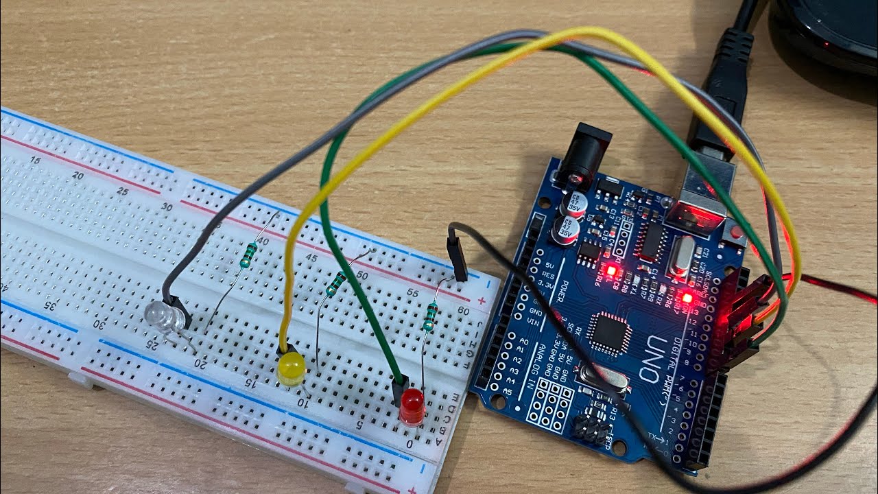
- 😀 The components required for this project include an Arduino, seven-segment display, traffic light model, flipboard, jumper cables, and a wiring diagram.
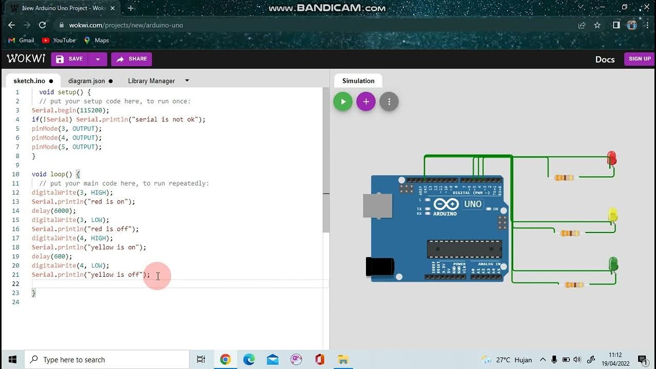
- 😀 The traffic light module has three LEDs: red (R), yellow (Y), and green (G), each connected to specific pins on the Arduino.
- 😀 For the traffic light module, the red LED connects to pin 5, yellow to pin 6, and green to pin 7 on the Arduino.
- 😀 The seven-segment display has four pins, labeled CLK, Dio, Bclk, and VCC, which connect to the Arduino pins 3, 4, 5, and GND respectively.
- 😀 The program for controlling the devices uses a library for the seven-segment display and defines pin connections for the LEDs and display.
- 😀 The program allows for a countdown or a forward count, which controls the state of the traffic light (red, yellow, green).
- 😀 The red light will turn off after the countdown reaches 6, while the yellow light will turn on.
- 😀 The video encourages viewers to follow the code link in the description and offers a brief explanation of the coding steps.
- 😀 Once the program is uploaded to the Arduino Uno, the traffic light simulation starts with the countdown, controlling the LEDs accordingly.
- 😀 The video ends with a call to action, asking viewers to like, share, and subscribe for more content.
Q & A
What is the purpose of the Arduino in this project?
-The Arduino serves as the controller for the traffic light system and the seven-segment display, managing the different signals (red, yellow, green) based on the code programmed.
Which components are necessary for the traffic light simulation?
-The necessary components include an Arduino board, a traffic light module, a seven-segment display, jumper wires, and a breadboard.
How are the traffic light module's pins connected to the Arduino?
-The traffic light module's pins are connected as follows: the 'R' pin (red) goes to pin 5 on Arduino, 'Y' (yellow) goes to pin 6, and 'G' (green) goes to pin 7. The ground (GND) is connected to the Arduino's GND.
What are the four pins of the seven-segment module, and how are they connected?
-The four pins of the seven-segment module are CLK, DIO, BCLK, and VCC. The CLK pin connects to pin 3, DIO connects to pin 4, BCLK connects to pin 5, and VCC connects to the 5V pin on the Arduino.
What is the role of the seven-segment display in the traffic light simulation?
-The seven-segment display shows a countdown or status of the traffic light sequence, indicating the number related to the light or action being performed.
What is the purpose of using the 'if' statement in the Arduino code?
-The 'if' statement in the Arduino code checks if the countdown number is less than 6 to turn off the red light and turns it on if the countdown is not less than 6.
What does the code do when the countdown reaches the number 6?
-When the countdown reaches the number 6, the red light turns off and the yellow or green light is activated, depending on the code logic.
Why does the creator emphasize using the brightest brightness setting?
-The creator uses the brightest brightness setting for visibility purposes, ensuring the lights and numbers on the display are easily visible during the simulation.
How is the traffic light simulation tested?
-After uploading the code to the Arduino, the simulation starts counting down from a defined number, and the lights change according to the defined logic. The system's behavior is tested by checking if the correct lights are activated at the appropriate times.
What should viewers do if they encounter issues with the tutorial?
-Viewers are encouraged to leave comments in the video’s comment section if they have any questions or if something is unclear in the tutorial.
Outlines

Cette section est réservée aux utilisateurs payants. Améliorez votre compte pour accéder à cette section.
Améliorer maintenantMindmap

Cette section est réservée aux utilisateurs payants. Améliorez votre compte pour accéder à cette section.
Améliorer maintenantKeywords

Cette section est réservée aux utilisateurs payants. Améliorez votre compte pour accéder à cette section.
Améliorer maintenantHighlights

Cette section est réservée aux utilisateurs payants. Améliorez votre compte pour accéder à cette section.
Améliorer maintenantTranscripts

Cette section est réservée aux utilisateurs payants. Améliorez votre compte pour accéder à cette section.
Améliorer maintenantVoir Plus de Vidéos Connexes

Simulasi Lampu Lalu Lintas Menggunakan Arduino UNO di Wokwi
SIMULASI PROJECT ARDUINO DENGAN WOKWI: LAMPU MERAH

[CUEE Camp 2nd] Part 2 : Condition and Loop
SIMULASI WOKWI MENGUANKAN BLYNK ARDUINO
Making Traffic Lights with Arduino Uno - Beginner Level (algorithm, coding, circuit design)

How to Make Simon Memory Game Using Arduino | Simon Says Game
5.0 / 5 (0 votes)
