Cara Menyolder SMD Menggunakan Solder Biasa Tanpa Mesin
Summary
TLDRThis tutorial guides viewers through the process of soldering a Surface-Mount Device (SMD) kit. The kit includes components like resistors, capacitors, ICs (NE555 and CD4017), and LEDs. The video demonstrates how to carefully position each component on the PCB, solder them with a fine-tipped soldering iron, and ensure correct polarity for LEDs. The presenter emphasizes using small tools like tweezers for precise placement, and the importance of accuracy in soldering, particularly for components like ICs. The final result is a running LED circuit, showcasing the skill of soldering tiny, delicate SMD components.
Takeaways
- 😀 This is a soldering practice kit for SMD (Surface Mount Device) components.
- 😀 The kit includes various components like a PCB, ICs (NE555, CD4017), resistors (1k, 10k, 2k), capacitors, LEDs, and a trimod AC.
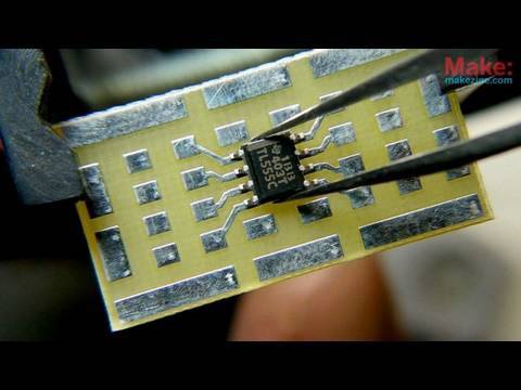
- 😀 SMD components are small and soldered directly onto the surface of the PCB, not through holes.
- 😀 The practice kit requires using a very fine-tip soldering iron (size 0.3mm or no0) for accuracy.
- 😀 Using tweezers is essential for positioning small components, especially resistors and capacitors.
- 😀 Soldering should start with the thinnest components, like resistors, and proceed to others like capacitors and ICs.
- 😀 Ensure that all components are correctly oriented before soldering, especially for polarized components like LEDs.
- 😀 The NE555 and CD4017 ICs need to be carefully placed with the correct orientation, indicated by marks on both the PCB and the components.
- 😀 Once the component is positioned, heat the soldering iron, press the component with tweezers, and solder the pins one at a time.
- 😀 After completing the soldering, the circuit can be tested, and the running LED effect can be observed, showing the working circuit.
- 😀 The tutorial encourages viewers to try the soldering practice and leave comments if they have questions or want to share their experience.
Q & A
What is the purpose of the SMD soldering kit?
-The SMD soldering kit is designed to help users practice soldering small SMD components on a PCB, simulating a real-world soldering experience despite using only hand tools.
What does SMD stand for, and how does it differ from other components?
-SMD stands for Surface Mount Device. Unlike traditional components with leads that go through holes in the PCB, SMD components are mounted directly on the surface of the PCB.
What is the size of the soldering tip recommended for this kit?
-A very fine tip, size no. 0, is recommended for soldering the small components, which are around 0.3 mm in size.
Why is it necessary to use tweezers when soldering SMD components?
-Tweezers are essential because SMD components are very small and delicate. They help position the components accurately on the pads before soldering them.
How should the components be soldered to the PCB?
-Each component should be soldered by first positioning it on the PCB pad and then heating it with the soldering iron. After ensuring it's in the correct position, solder the component's leads to the pads.
What should be done if a component is installed incorrectly?
-If a component is installed incorrectly, such as a resistor or capacitor being reversed, it is not typically a problem for non-polar components. However, for polar components like LEDs, orientation must be checked to avoid mistakes.
How should the soldering process be performed for resistors?
-The soldering process for resistors involves placing the resistor on the PCB pad, heating it with the soldering iron, and then soldering both ends. The process is repeated for all resistors on the board.
What is the significance of the small dot on certain components like the ICs?
-The small dot on components like ICs serves as a guide to ensure proper orientation during installation. It helps align the component with the PCB correctly, avoiding mistakes in placement.
What is the recommended method for soldering the LED?
-When soldering the LED, the shorter leg should be connected to the negative side (marked with a minus sign), and the longer leg to the positive side. The process is similar to soldering other components—first solder one leg, then the other.
What does the finished project look like after all components are soldered?
-The finished project should have all components securely soldered on the PCB, with the LED functioning as a running light indicator, which can be controlled or adjusted as needed.
Outlines

Cette section est réservée aux utilisateurs payants. Améliorez votre compte pour accéder à cette section.
Améliorer maintenantMindmap

Cette section est réservée aux utilisateurs payants. Améliorez votre compte pour accéder à cette section.
Améliorer maintenantKeywords

Cette section est réservée aux utilisateurs payants. Améliorez votre compte pour accéder à cette section.
Améliorer maintenantHighlights

Cette section est réservée aux utilisateurs payants. Améliorez votre compte pour accéder à cette section.
Améliorer maintenantTranscripts

Cette section est réservée aux utilisateurs payants. Améliorez votre compte pour accéder à cette section.
Améliorer maintenantVoir Plus de Vidéos Connexes
Circuit Skills: Surface Mount Devices
Lec 63: Familiarity with Components - I

Belajar Komponen SMD, Apa itu THT & SMT juga SMD?, Mengenal komponen SMD

Cara membuat vacum cleaner dengan mudah

Tutorial Cara Merakit DIY KIT Robot Line Tracer Follower Cocok Untuk Pemula Belajar Solder Edukasi

Surface Mount Assembly Process Step by Step
5.0 / 5 (0 votes)
