Beginner Electronics - 10 - Bread Boards
Summary
TLDRIn this electronics tutorial, Gautam Ord introduces viewers to the basics of breadboards, essential tools for circuit building. He explains the structure of breadboards, highlighting the connected holes and power rails. A practical demonstration follows, where Gautam recreates a circuit from a previous episode on a breadboard, connecting a 9-volt battery to an LED with a resistor. The video serves as a beginner's guide to understanding and using breadboards for electronic prototyping.
Takeaways
- đ The video is an educational tutorial focused on breadboards, a fundamental tool in electronics.
- đ Breadboards are important for creating and testing circuits due to their ability to hold components and wires securely.
- đ The script explains that breadboards have holes connected in specific ways to allow for circuit creation, with power rails and internal metal strips facilitating connections.
- đąđŽ The power rails, typically red and blue, are long metal strips that connect all holes in a row, allowing for continuous power supply across the breadboard.
- đč The main part of the breadboard consists of rows with five holes each, which are connected internally, facilitating the creation of circuits.
- đ The upper and lower sections of the breadboard are separate, meaning components plugged into the top and bottom rows are not interconnected.
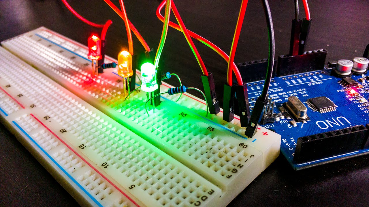
- đ The tutorial demonstrates how to build a circuit on a breadboard, starting with connecting a 9-volt battery to the power rails.
- đĄ The LED's longer lead is connected to the positive rail, and a resistor is used to limit the current, highlighting the importance of correct component orientation and placement.
- đ Wires are used to connect the LED and resistor to complete the circuit, emphasizing the role of wires in bridging connections on a breadboard.
- âš The video concludes with a successful demonstration of an LED lighting up, showcasing the practical application of breadboard circuitry.
- đ The presenter encourages viewers to ask questions in the comments, emphasizing the importance of understanding breadboards for electronic prototyping.
Q & A
What is the main focus of this electronics tutorial?
-The main focus of this electronics tutorial is to teach about breadboards, their importance, and how they work.
What is a breadboard and why is it important in electronics?
-A breadboard is a versatile and reusable device used in electronics for prototyping and testing circuits. It's important because it allows for easy and quick assembly and modification of circuits without soldering.
How are the holes in a breadboard connected?
-The holes in a breadboard are connected in specific ways. The power rails (or buses) at the top and bottom are connected across their entire length, while the central part of the breadboard has rows of five holes connected internally, with these rows separated from each other.
What are the power rails on a breadboard and how are they used?
-The power rails on a breadboard are long metal strips that run along the top and bottom edges of the board. They are used to provide power to the circuit, often by connecting the positive and negative terminals of a battery or power supply.
How does the presenter demonstrate the connection of wires on the power rails?
-The presenter demonstrates by connecting a 9-volt battery to the breadboard, with the positive terminal inserted into the red rail and the negative terminal into the blue rail, showing that wires in these holes are connected.
What is the significance of the color coding (red and blue) on the power rails?
-The color coding (red and blue) on the power rails typically indicates polarity, with red often representing the positive rail and blue representing the negative rail, helping to avoid confusion when connecting power sources.
How does the presenter ensure the LED lights up in the circuit?
-The presenter ensures the LED lights up by correctly connecting the longer lead of the LED to the positive rail, the shorter lead to a row on the breadboard, and a resistor to manage the current, completing the circuit with a wire to the negative rail.
What is the purpose of the resistor in the circuit demonstrated in the tutorial?
-The purpose of the resistor in the circuit is to limit the current flowing through the LED, preventing it from drawing too much power and potentially burning out.
How does the presenter suggest using breadboards for circuit prototyping?
-The presenter suggests using breadboards for prototyping by demonstrating how to easily build and modify circuits without the need for soldering, allowing for quick testing and iteration of electronic designs.
What is the advice given by the presenter for viewers who have questions about breadboards?
-The presenter encourages viewers to leave their questions in the comments section of the video, indicating a willingness to engage with the audience and provide further clarifications.
Outlines
đ Introduction to Breadboards
In this segment, Gautam Ord introduces the topic of breadboards, emphasizing their importance in electronics. He invites viewers to ask questions in the comments section and previews a circuit rebuild from a previous episode. A diagram is presented to explain the structure of a breadboard, highlighting the interconnected holes that facilitate circuit creation. The power rails, or buses, are described as long metal strips that run along the top and bottom edges of the breadboard, connecting all holes in their respective rows. This allows for easy connection of wires to a power source, such as a battery. The main body of the breadboard, which contains rows of five holes each, is also explained, noting that these holes are connected in a way that enables the creation of circuits. The video aims to clarify the layout and functionality of breadboards for viewers, with a focus on their practical use in building electronic circuits.
đ© Building Circuits with Breadboards
This part of the script details the process of building a circuit using a breadboard. The presenter explains the layout of the breadboard, focusing on the power rails and the rows of five holes that are connected. He demonstrates how to connect a 9-volt battery to the breadboard by inserting the positive terminal into the red rail and the negative terminal into the blue rail. The assembly of an LED with a resistor is then shown, with the longer lead of the LED connected to the positive rail and the shorter lead placed in a regular row. A resistor is added to the circuit, connected to the LED and spanning across to another row. Finally, a pre-cut wire is used to complete the circuit by connecting the resistor to the negative rail, resulting in the LED lighting up. The presenter encourages viewers to ask questions about breadboards, highlighting their utility in prototyping electronic projects.
Mindmap
Keywords
đĄBreadboard
đĄHoles
đĄPower Rails
đĄWires
đĄLED
đĄResistor
đĄCircuit
đĄBattery
đĄBattery Holder
đĄConnections
đĄPrototype
Highlights
Introduction to breadboards and their importance in electronics.
Invitation for viewers to ask questions in the comments section.
Explanation of how to rebuild a circuit from a previous tutorial on a breadboard.
Visual representation of a breadboard and its components.
Description of the connectivity of holes in a breadboard.
Explanation of power rails and their function in a breadboard.
Detail on how power rails connect holes across the entire length of the breadboard.
Clarification on the separation of power rails and their independent connections.
Discussion on the main part of the breadboard and its five-hole connection pattern.
Emphasis on the separation of the upper and lower sections of the breadboard.
Instruction on how to connect a battery to a breadboard using power rails.
Demonstration of connecting an LED to a breadboard.
Explanation of the necessity of a resistor when connecting an LED.
Step-by-step guide on assembling a circuit on a breadboard.
Completion of the circuit and the lighting of the LED.
Comparison of the breadboard method to previous methods, highlighting its cleanliness and efficiency.
Encouragement for viewers to become familiar with breadboards for electronic prototyping.
Transcripts
what's going on everyone my name is
Gautam Ord welcome back to electronics
episode 10 in this episode we are going
to learn all about bread boards bread
boards are really really important to
understand so if you have any questions
whatsoever throughout this tutorial
leave them down below in the comments
and at the end of this video we are even
going to rebuild the circuit that we
built in episode 8 on the breadboard so
stay tuned here I have an image that
represents a breadboard now you already
saw a breadboard in the previous video
so if you forget what it looked like go
back to that video and you can check it
out and this is just kind of a quick
diagram basically all of these little
circles here are little holes that you
can input a wire into you can plug a
wire into each one of the little holes
on the breadboard now these holes are
connected in specific ways that allow
you to create circuits first let's take
a look at the power rails basically this
area up here and the breadboard in this
area down here these are called power
rails or buses and they're basically
really long strips of metal so what I
mean by that is the power rail up here
basically all of these holes that I'm
highlighting in green all of those holes
throughout the whole entire breadboard
are all connected to each other that
means if I plug a wire into this hole
and I plug a wire into this hole they're
basically on the same wire because
there's a metal piece connecting all of
these holes together so that would make
a connection these two wires in these
two holes would be connected to each
other and that goes the same for the row
below all of these holes that I'm
highlighting are also connected to each
other so if we plugged a hole or a
plugged a wire into here and into here
they're connected to each other they
make a connection but these two rails
are separate because if we plug a wire
into this hole right here and we also
plug a wire into this hole those two
wires are not connected they are not
connected because remember only this row
up here are connected to each other and
this row down here are connected to each
other that's the only things that those
holes are connected with and it works
the exact same for the power rail or bus
down and this end too so basically on
the edges of almost every breadboard not
all of them but almost every breadboard
you have power rails that
basically extend down the whole board
connecting all of those holes and that's
generally where you plug in your battery
source so generally you would plug in
the positive terminal of your battery
here and the negative terminal of your
battery right here that way you can get
power throughout the whole length of
your breadboard
all right now let's talk about the part
that you're really going going to be
using a lot and that is this main part
of the breadboard here these two rows of
a bunch of holes most breadboards like
this one and the ones that I'm going to
be using have five holes in every row
like so as you can see basically every
five holes are connected so these five
holes right here are all connected these
five holes right here they're all
connected as well these five holes are
all connected these five holes are all
connected and it goes like that all the
way down in rows these five holes right
these five holes right here etc however
these two sections this upper section
right here and this lower section are
separate from each other so if I plugged
a wire into this hole right here and I
plugged a wire into this hole right here
they are not connected however if I
plugged a wire into this hole right here
and a wire into this hole right here
they are connected so basically every
five holes in a little row like this
they're connected by a little metal
strip within the breadboard so any wires
you plug into them will be connected on
the other hand if you try connecting
wires the opposite way so we plug a wire
into this hole and we plug a wire into
this hole right here they are not
connected because these middle areas are
only connected in rows that go extend up
and down like so I really hope that I'm
making this clear I know I'm not the
best explainer when it comes to physical
objects like a breadboard
I hope I'm explaining it good enough
basically every five holes are connected
by a little metal strip so anything you
plug into them will be on the same wire
pretty much and the power rails extend
for the length of the breadboard and
they have a long metal strip within the
breadboard as well again I hope I made
that clear if you have any questions
whatsoever please let me know down below
in the comments now let's move on to the
actual circuit building on a breadboard
we actually build a circuit on a
breadboard all right so now that we know
exactly how a breadboard is laid out and
how they kind of work let's build the
same circuit that we did in tutorial
eight on the breadboard here I have a
9-volt battery connected to a 9-volt
battery holder which basically just
gives me the two leads off of it I have
my breadboard here my LED and my
resistor as well as a couple of wires
just in case I'm going to need them so
as you can see on this specific
breadboard we have two power rails on
basically either side one is marked red
and one of the smart blue and on this
particular breadboard and our most
breadboards these power rails run the
metal strips all the way down them like
we've already explained whereas these
little rows going up and down just these
tiny little rows of five little holes
are connected to each other and they're
separated on both sides so these five
are different from these five right here
I've already explained how these
breadboards are laid out it's just a
little while until you begin to make
sense of how all these connections go
now because these power rails are meant
for power I'm going to plug my battery
right on into there the positive
terminal of my 9-volt battery is going
to go into the red rail and the negative
terminal of my 9-volt battery is going
to go into the negative rail or the blue
rail hair on my breadboard like so I'm
going to zoom in just a bit so that we
can see everything a bit more clearly so
now we have essentially the positive
terminal of my battery connected to this
far rail right here up running up and
down and the negative terminal of my
battery connected to this nearer rail
right here running up and down the
breadboard next I'm going to insert my
LED remember the longer lead always gets
connected to positive so I'm going to
take my LED here I'm going to stick the
longer lead right on into the positive
rail as you can see and I'm going to
stick the other lead into one of the
holes on one of the regular rows on the
breadboard if I rotate this a little bit
you'll see that the longer lead is
connected to the positive terminal and
the other lead is just connected to one
of the rows on the breadboard now of
course this LED is going to need a
resistor so I'm going to take my
resistor as well I'm just going to bend
the leads a little bit I'm going to
attach it to in this case my negative
terminal of my LED and I'm just going to
turn it around and I'm just going to pop
it into another set of five holes on my
breadboard here
rrrow like so hopefully you are able to
see that maybe if I focus a bit more
there we go the LED is connected or I'm
sorry the resistor is connected to the
LED and then it ranges over and it's
really hard to see and I really
apologize for that as you can see it
runs into this row right here as well
now to complete our circuit I'm just
going to use one of my fancy little
breadboard wires here pre-cut and pre
stripped for me and I'm going to attach
to the same row as the resistor here so
I'm just going to plug that into the
same rail and I should be able to plug
this into the negative terminal row like
so and if it'll stay in there we have
our LED lighting up so this is the same
circuit that we created in episode 8
except look at that it's much more
cleaner we didn't have to use any clips
or hold anything with our fingers it's
sitting there and it's working now again
I really apologize if you can't see the
wires too too well so if you have any
questions whatsoever on breadboards
please leave them down below in the
comments because bread boards are your
friend you really need to get used to
using them and how they're laid out so
now that we know about bread boards were
able to prototype almost anything
electronic that we want so let's
continue on with this tutorial series
thanks for watching everyone else see
you guys in the next tutorial
Voir Plus de Vidéos Connexes
Beginner Electronics - 8 - First Circuit!
Beginner Electronics - 3 - Closed/Open Circuits
Proses pengisian dan pengeluaran daya pada kapasitor
Complete beginner's guide to using a breadboard
How To Drive A 7-segment Display - The Learning Circuit
Alat sederhana tapi sangat berguna.PLN JANGAN SAMPAI TAU !!
5.0 / 5 (0 votes)