Understanding GD&T
Summary
TLDRThis script offers an in-depth exploration of Geometric Dimensioning and Tolerancing (GD&T), a critical aspect of mechanical design ensuring parts fit and function correctly. It explains the shift from traditional dimensional tolerancing to GD&T, which accounts for a part's intended function by controlling 14 geometric characteristics across five categories: Form, Orientation, Location, Profile, and Runout. The video delves into the application of GD&T, including feature control frames, datums, modifiers, and inspection techniques, providing a comprehensive foundation for mechanical designers.
Takeaways
- 🔍 Tolerances are critical in mechanical design to ensure parts fit and function as intended.
- 📏 Dimensional tolerancing has limitations as it doesn't account for how parts will be used in practice.
- 📐 Geometric Dimensioning and Tolerancing (GD&T) is a more functional approach, controlling 14 different geometric characteristics.
- 🔺 GD&T categorizes these characteristics into Form, Orientation, Location, Profile, and Runout.
- 📋 Features in GD&T can be surfaces, holes, or slots, and are controlled using feature control frames.
- 🔳 Surface features are individual surfaces, while features of size have defined dimensions and can be measured.
- 🔲 Geometric tolerances applied to surface features or features of size can have different implications.
- 📏 Datums are reference surfaces used during inspection and are crucial for establishing a part's position and orientation.
- 🔄 Modifiers in GD&T, like MMC and LMC, can adjust tolerance zones based on the feature's size relative to its limits.
- 🔍 The Envelope Principle in ASME ensures parts fit together by controlling both size and form, unlike ISO's Independency Principle.
Q & A
What is the primary challenge in designing and building mechanical systems?
-The primary challenge in designing and building mechanical systems is ensuring that all parts, once manufactured, will fit together and function as intended.
Why is tolerancing important in the mechanical design process?
-Tolerancing is important because it allows for variations in manufacturing while still ensuring that parts will fit together and function correctly.
How does geometric dimensioning and tolerancing (GD&T) differ from dimensional tolerancing?
-GD&T differs from dimensional tolerancing by allowing control of tolerances in a way that reflects the intended function of the part, rather than just defining how much each dimension can deviate from its nominal value.
What are the five categories of geometric characteristics controlled by GD&T?
-The five categories of geometric characteristics controlled by GD&T are Form, Orientation, Location, Profile, and Runout.
What is the difference between surface features and features of size in GD&T?
-Surface features in GD&T are individual surfaces, while features of size are features that have a defined dimension and can be measured with tools like calipers.
How are geometric tolerances applied to features in GD&T?
-Geometric tolerances in GD&T are applied to features using feature control frames, which contain all the necessary information to control a specific geometric characteristic.
What is the purpose of datums in GD&T?
-Datums in GD&T are reference surfaces that need to be considered during inspection. They are used to locate features and define how a part should be immobilized when inspecting a geometric tolerance.
How does the Envelope Principle, also known as GD&T Rule Number 1, affect the form of a feature?
-The Envelope Principle states that the surface of a regular feature of size shall not extend beyond an envelope that is a boundary of perfect form at MMC, meaning that the MMC limit of size controls both the size and form of the feature.
What is the difference between the Envelope Principle and the Independency Principle?
-The Envelope Principle states that the size limits control the form of a feature, while the Independency Principle considers the geometric form and size of a feature separately, meaning that the size limits do not control form.
What are the two types of runout tolerances and how do they differ?
-The two types of runout tolerances are circular runout and total runout. Circular runout controls the roundness of individual cross-sections relative to a datum axis, while total runout controls runout along the axial direction, using a tolerance zone defined by two concentric cylinders.
Outlines
🔍 Introduction to Mechanical Design and Tolerances
This paragraph introduces the complexity of mechanical system design, emphasizing the importance of tolerancing to ensure parts fit and function correctly. It contrasts dimensional tolerancing with geometric dimensioning and tolerancing (GD&T), highlighting GD&T's ability to control tolerances based on a part's intended function. GD&T focuses on 14 different geometric characteristics, categorized into Form, Orientation, Location, Profile, and Runout. The paragraph explains the difference between surface features and features of size, and how geometric tolerances are applied using feature control frames, which include symbols for geometric characteristics, tolerance values, datums, and modifiers.
📏 Understanding Geometric Tolerances and Datums
The second paragraph delves into the specifics of geometric tolerances within the Form category, discussing flatness, straightness, circularity, and cylindricity. It explains how these tolerances are applied and inspected, using tools like dial test indicators and coordinate measuring machines (CMMs). The paragraph also introduces the concept of datums, which are reference surfaces used during inspection to immobilize a part and ensure accurate measurement. Datums are identified with letters and symbols on drawings and can be actual surfaces or theoretical perfect surfaces, with datum simulators being the real, imperfect surfaces used for immobilization.
🛠️ Controlling Feature Geometry with Datums and Orientation Tolerances
This paragraph continues the discussion on datums, explaining the difference between a datum feature, a datum, and a datum simulator. It describes how restraining datum features reduces a part's degrees of freedom, allowing for accurate inspection. The paragraph then moves on to orientation tolerances, which control the angles between features and datums, including parallelism, perpendicularity, and angularity. It outlines how these tolerances are inspected, using methods like sine bars and by placing parts on datum simulators.
🔩 Position Tolerances and the Benefits of Geometric Tolerance Approach
The fourth paragraph focuses on position tolerances, which define the acceptable location of a feature of size relative to its true position. It contrasts the geometric tolerance approach with traditional dimensional tolerances, highlighting the advantages of using cylindrical tolerance zones and the ability to explicitly define relevant datums and their order. The paragraph also introduces modifiers in GD&T, such as MMC and LMC, which adjust tolerance zones based on the actual size of a feature, providing flexibility and ensuring parts fit together properly.
🔄 The Envelope Principle and Modifiers in GD&T
This paragraph discusses the Envelope Principle from the ASME standard, which states that a feature's surface must not extend beyond a boundary of perfect form at the maximum material condition (MMC). It contrasts this with the ISO standard's Independency Principle, which considers geometric form and size separately. The paragraph explains how modifiers like E and I can be used to apply the Envelope or Independency principles, respectively. It also touches on special cases where the Envelope Principle is overwritten, such as when explicit flatness or straightness tolerances are called out for a feature of size.
🌐 Profile and Runout Tolerances in GD&T
The final paragraph covers profile and runout tolerances, which are versatile and can control form, orientation, and location simultaneously. It explains how profile of a surface and profile of a line tolerances create tolerance zones that follow the shape of the feature. The paragraph also discusses runout tolerances, including circular runout and total runout, which control eccentricity relative to a datum axis. It mentions inspection methods for these tolerances, such as using dial gauges. The paragraph concludes by acknowledging the complexity of GD&T and encourages viewers to explore further resources, including exclusive content on Nebula and a special offer for CuriosityStream.
Mindmap
Keywords
💡Tolerancing
💡Dimensional Tolering
💡Geometric Dimensioning and Tolerancing (GD&T)
💡Features
💡Feature Control Frames
💡Datums
💡Modifiers
💡Flatness
💡Straightness
💡Cylindricity
💡Position Tolerance
Highlights
Tolerancing is crucial for ensuring parts fit and function as intended in mechanical design.
Dimensional tolerancing defines how much each dimension can deviate from its nominal value.
Geometric Dimensioning and Tolerancing (GD&T) complements dimensional tolerancing by controlling 14 different geometric characteristics.
GD&T allows for better communication of design aspects by applying tolerances to features like surfaces, holes, or slots.
Geometric tolerances are assigned using feature control frames that contain all necessary control information.
Flatness tolerance defines a tolerance zone between two parallel planes for surface features.
Straightness tolerance is applied to individual lines on a surface feature, defining a tolerance zone between two parallel lines.
Circularity tolerance controls the roundness of a surface with a tolerance zone defined by two concentric circles.
Cylindricity is similar to circularity but with a uniform tolerance zone along the full length of the feature.
Datums are reference surfaces used during inspection and are identified on drawings with a letter and symbol.
Position tolerance defines the maximum distance a feature of size can be located away from its theoretically exact position.
Modifiers in GD&T allow for additional bonus tolerance depending on how close the feature is to its size limits.
The Envelope Principle in ASME states that a feature's surface must not extend beyond a boundary of perfect form at MMC.
Profile tolerances control form, orientation, and location of features with a tolerance zone following the shape of the feature.
Runout tolerances describe the eccentricity of a surface relative to an axis and are used for rotating parts like shafts.
GD&T is complex, but understanding its fundamentals is essential for accurate mechanical design and manufacturing.
Transcripts
Designing and building any kind of mechanical system is a complex process that needs to properly
account for many different parameters, like cost, materials, and manufacturing techniques.
But one of the key challenges is making sure that all of the parts,
once manufactured, will fit together and function as intended.
And that's why tolerancing is such an important part of the mechanical design process.
The easiest way to define tolerances is using the dimensional approach,
where drawings define how much each dimension of a part is allowed to deviate from its nominal value.
But dimensional tolerancing doesn't work particularly well in a lot of scenarios because
it doesn't really reflect how the part will be used. It doesn't let you specify that you need a
surface to be flat because it has to create a seal with another part, for example, or let you control
how close to perpendicular the axis of a hole needs to be to the surface it's drilled into.
Geometric dimensioning and tolerancing, usually called GD&T, is a different
approach to tolerancing that allows you to control tolerances in a way that reflects the
intended function of the part. It complements dimensional tolerancing by letting you control
14 different geometric characteristics, helping you better communicate which aspects
of your design are important. These characteristics can be
split into 5 categories that control Form, Orientation, Location, Profile and Runout.
Unlike the traditional tolerancing approach that applies tolerances to dimensions, GD&T
applies them to features instead. A feature could be a surface, a hole, or a slot, for example.
It's important to differentiate between surface features, which are just individual surfaces,
and features of size, which are any features that have a defined dimension,
meaning that they can be measured with callipers, whether that's a hole, or a feature defined by two
opposed parallel surfaces. This is because in the GD&T world geometric tolerances can
mean very different things if they're applied to surface features or to features of size.
Geometric tolerances are assigned to features using feature control frames. These little grids
contain all of the information needed to fully control a particular geometric characteristic.
They can be applied to features using leader lines,
extension lines, or for features of size they can be attached directly to dimensions.
Let's look at how they're structured. The first box in the frame contains a symbol
that defines which of the 14 geometric characteristics is being controlled.
The next box specifies the tolerance to apply. This value defines the size
of a tolerance zone within which the entirety of the feature must be located.
The shape of the zone depends on the geometric characteristic being controlled - a diameter
symbol can be added to indicate that the tolerance zone is circular or cylindrical.
Next is a series of letters that defines datums, the reference surfaces that need
to be considered during inspection. And finally modifiers can be added to
either the tolerance or to the datums, to get even more control over tolerancing.
We'll talk about datums and modifiers in more detail later on, but first let's look at an
example, starting with one of the simpler geometric characteristics, flatness.
The feature control frame for a flatness call-out looks like this.
When the call-out is applied to a surface it defines a tolerance zone between two parallel
planes that are separated by the distance shown in the feature control frame.
All manufactured parts are imperfect – for a part to meet this tolerance
all points on the surface must be located within the tolerance zone.
The two planes defining the tolerance zone are parallel
to each other, but they don't have to be parallel to any other surfaces.
Flatness tolerances are often specified on surfaces that mate
with other parts and need to have even contact, like the face of a flange.
Flatness tolerances can also be applied to features of size, in which case the tolerance
zone applies to the derived median plane of the feature. The derived median plane is constructed
by taking the midpoints of opposite points on the two surfaces that define the feature of size.
Since the surfaces are imperfect, the derived median plane will be too.
When learning about GD&T it's often useful to think about how
a part will be inspected to see if it meets the geometric tolerance.
Flatness of a surface can easily be measured using a dial test indicator. First the part is mounted
on three jacks, and the jacks are adjusted so that the indicator reads zero at three defined points.
This creates a reference plane.
The indicator is then swept across the surface to identify high and low points.
If the distance between the highest and lowest points is less than the
width of the tolerance zone, the flatness requirement is met.
Another very common inspection approach is to use a CMM, a coordinate measuring machine.
A computerised probe is used to take measurements that are fed into software
that then uses algorithms and curve fitting to determine deviations from the perfect size.
CMMs are expensive pieces of equipment but can be used to inspect any kind of geometric tolerance.
Next in the Form category of geometric tolerances is Straightness. It's similar to Flatness,
but is applied to individual lines instead of to an entire surface.
When applied to a surface feature, any line on the surface in the same direction as the
line the call-out is pointing at must be within a tolerance zone defined by two parallel lines.
For inspection the probe is swept along multiple straight lines instead of being swept across the
entire surface.
When straightness is applied to a feature of size instead of a surface,
the tolerance zone is cylindrical and it applies to the axis of the feature.
You might apply a straightness tolerance to the axis of a pin,
for example, to make sure it will engage properly with a hole.
The circularity tolerance is used to control how round a surface is.
The tolerance zone is defined by two concentric circles,
the radial distance between the two circles being equal to the specified tolerance.
Circularity controls the roundness of individual cross-sections completely independently.
This means the tolerance zones don't need to be on the same axis,
and the diameter of the concentric circles can vary along the length of the feature.
Circularity can be inspected in a few different ways but ideally the part should be rotated and
a probe used to measure displacements at several different cross-sections.
The measurements are plotted on a polar graph to determine if the tolerance is met.
Cylindricity is the last of the four form tolerances. It's similar to circularity
except the tolerance zone is uniform along the full length of the feature.
Form tolerances control the shape of a single surface,
axis or plane. But most other tolerance types control the geometry of a feature relative to
one or more references, that are called datums.
Datums are identified on drawings using a letter and this triangle symbol,
and can be attached to features in a few different ways.
Datums are usually defined using surfaces, but if the symbol is attached to a feature
of size the datum is the corresponding centreline or centre plane.
Datums are used to locate features by defining how a part should be immobilised when inspecting
a geometric tolerance. To be accurate with the terminology we need to differentiate between
a datum feature, which is the feature on the object that's restrained, a datum, which is the
theoretical perfect surface corresponding to that feature, and a datum simulator, which is a real
imperfect surface that will be used to immobilise the part to approximate the perfect datum.
A part just floating in space is said to have six degrees of freedom - it can translate left
and right, up and down, and forward and back, and it can rotate around those three axes.
If we hold the datum feature against a datum simulator, three of the six degrees of freedom are
immobilised. The part can now only translate left and right, and up and down, and it can only rotate
around a single axis. Restraining one more datum feature constrains another two degrees of freedom.
And by restraining a third the part is fully immobilised and can be inspected.
These datums establish a datum reference frame,
the coordinate system used to inspect the feature.
The order in which the datums are applied is important because all real surfaces are
imperfect - using datums in the same order ensures that measurements are repeatable. To see why let's
look at an example where we want to measure where the centre of the hole is located.
Since we held the part against datum simulator B
first it will have a minimum of three contact points with datum feature B.
Datum simulator C will have a minimum of two contact points with datum feature C,
and datum simulator F will have a minimum of one contact point with datum feature F.
The datums are listed in order in the feature control frame.
If we change the order in which the datums are applied, or if we use different datums,
the part will be set up slightly differently for measurement.
All of the remaining geometric tolerances use datums. Let's look at the orientation
group of tolerances next. They're used to control the angles between features.
Parallelism controls how close a feature is to being parallel to a datum.
The tolerance zone is defined by two planes that are parallel to the specified datum.
Perpendicularity works in the same way, but the tolerance zone is at 90 degrees to the datum.
And angularity is a more general orientation
tolerance that controls the angle between a feature and a datum.
When applied to features of size, the orientation tolerances apply to the centre
plane or axis of the feature. The diameter symbol is used in this feature control frame
to specify that the tolerance zone for the axis of the feature is cylindrical.
To meet the tolerance the axis must be contained within the tolerance zone.
Parallelism is inspected in a similar way to Flatness, but instead of mounting the
part on jacks the datum feature on the part is placed directly on the datum simulator.
Perpendicularity can be checked in the same way.
And angularity can be checked using a sine bar, that allows angles to be measured accurately.
There are three location tolerances - position, concentricity and symmetry.
Although they all appear in the ISO standards, the concentricity and symmetry tolerances were
removed from the 2018 edition of ASME Y14.5, so I won't cover them in this video.
Position is one of the most commonly used geometric tolerances. It defines
the maximum distance the axis or median plane of a feature of size can be located away from
its theoretically exact position. It's often applied to control the location of holes.
The theoretically exact position of the feature,
called the true position, is defined using basic dimensions,
which are enclosed in a box to show that normal dimensional tolerances don't apply to them.
The position tolerance establishes a cylindrical tolerance zone around the true position.
To be acceptable the axis of the hole must be contained within the tolerance zone.
The position of a hole can obviously be defined using dimensional "plus and minus" tolerances,
so you might be wondering why the geometric tolerance approach is
any better. There are a few reasons. One big advantage is that dimensional
tolerances define a rectangular tolerance zone, but in almost all cases it makes more sense to use
a cylindrical zone, which is evenly distributed around the true position of the hole.
Another advantage of the geometric tolerance approach is that it allows you to explicitly
define the relevant datums and the order in which they should be considered.
For holes the primary datum is usually chosen to be the datum perpendicular to
the axis of the hole, because the hole axis being perpendicular to the mating
surface is usually more important than its position on the surface.
And finally, using a position tolerance allows a bonus tolerance
to be gained by applying modifiers. Modifiers are an important part of GD&T
that allow the tolerance zones applied to features of size to be increased by
an additional bonus tolerance, depending on how close the feature is to its size limits.
This hole is a feature of size, and its limits of size are defined by dimensional tolerances.
The hole has a maximum allowable diameter of 9.8 millimetres, and a
minimum allowable diameter of 9.2 millimetres.
GD&T identifies three different conditions for any feature of size - a maximum material
condition, a least material condition and a regardless of feature size condition.
The maximum material condition occurs when the feature is at the size limit where it has the
most amount of material. For a hole this is the smallest allowable hole size. And for a pin it's
the largest allowable diameter. The least material condition is the
opposite case where the feature has the smallest allowable amount of material.
By default geometric tolerances apply at the Regardless of Feature Size condition,
meaning that the size of the tolerance zone is defined by the tolerance value
in the feature control frame, and it doesn't change.
But this behaviour can be adjusted by including a modifier, either the letter
M for MMC or the letter L for LMC, next to the tolerance in the feature control frame,
which adds a bonus tolerance to the tolerance zone depending on the actual size of the feature.
Let's look at an example for MMC, which is the most commonly used modifier.
Here it's applied to the position of a hole.
The modifier means that the tolerance zone in the feature control frame applies at the
maximum material condition, which is the smallest allowable hole.
If the hole is larger than MMC, a bonus tolerance is added to the position tolerance that's equal
to the difference between the actual size of the feature and the maximum material condition.
One common use of the MMC modifier is where it's applied to benefit from the fact that a hole
is oversized, and so its position can be less accurate and still fit with a mating part.
The LMC modifier is less commonly used but works in a similar way.
It adds bonus tolerance when the actual size of the feature has more material.
This can be used if you have a hole close to an edge for example, and you need to apply a tight
tolerance to the position of the hole to make sure there's sufficient material between the
hole and the edge, but you want to relax the tolerance if the hole is smaller.
The MMC and LMC material modifiers can be applied to other tolerance types like
flatness or perpendicularity, and can even be applied to datums if they're features of size,
although that's outside of the scope of this video.
Material modifiers aren't the only way that the form of a feature can be affected by its
size. A key concept that appears in the ASME standard is the Envelope Principle, which is
also referred to as GD&T Rule Number 1. It states that "the surface or surfaces of a regular feature
of size shall not extend beyond an envelope that is a boundary of perfect form at MMC".
Let's look at an example to see what this means. This pin has a nominal size of 12
millimetres with a dimensional tolerance of plus or minus half a millimetre.
Rule Number 1 establishes an envelope around the pin based on the maximum material condition,
which is the largest possible diameter of 12.5 millimetres. According to Rule Number 1,
no part of the pin surface is allowed to extend beyond this envelope.
This means that the MMC limit of size controls not only the size but also the form of the pin.
If the actual size of a manufactured pin is 12.5 millimetres, meaning that it's at MMC,
then it will need to have perfect form to fit into the envelope.
If the actual size of the pin is smaller than MMC, the pin doesn't have to have perfect
form - it can be slightly bent, or barreled, for example. To be acceptable the pin has to
be within the limits of size, be contained within the MMC envelope, and meet any other
geometric tolerances that have been defined. Rule number 1 is the default behaviour in the
ASME standard, and its purpose is to ensure that parts will fit together properly. This
pin will always fit in a hole that's larger than the MMC envelope.
The ISO standard works differently - it uses the Independency Principle by default,
where the geometric form and the size of a feature are considered separately.
When using this approach the limits of size do not control form at all. The pin could be
completely bent and still acceptable so long as it is within the limits of size. When using the
Independency Principle there's no guarantee that the pin will fit in a hole larger than the MMC
envelope. Additional geometric tolerances need to be applied to control how straight the pin is.
Modifiers can be used to change the default behaviour. If the E modifier is used on a
drawing to the ISO standard, it means that the Envelope Principle applies.
And if the I modifier is used on a drawing to the
ASME standard it means that the Independency Principle applies.
ASME defines a few other special cases where the Envelope Principle is overwritten - for example
if a flatness or straightness tolerance has been called out explicitly for a feature of size.
But anyway that's enough about modifiers and the Envelope Principle - let's go
through the remaining tolerance types. Profile tolerances are very versatile and
can be used to control the form, orientation and location of features all at the same time.
The Profile of a Surface tolerance creates a tolerance zone that follows the shape of
the toleranced feature, with a width equal to the specified tolerance.
Profile of a Line is similar to Profile of a Surface, but it controls individual
line elements of a surface, instead of the entire surface at once.
The inspection of complex profile tolerances can be difficult without a CMM, although
it really depends on the application and the complexity of the surface.
In some cases profile tolerances can be used instead of other tolerance types.
Applying a Profile of a Surface tolerance to a single nominally flat surface without datums,
for example, is the same as applying a flatness tolerance.
Finally we have the runout category of tolerances.
Runout is a term used to describe the eccentricity of a surface relative to a particular axis.
There are two runout tolerances, circular runout, and total runout.
Circular runout controls the roundness of individual cross-sections of a feature
relative to a datum axis. In this case the datum axis is defined by datum feature A.
The tolerance zone is defined by two concentric circles.
This is similar to the circularity tolerance zone,
except that circular run-out uses datums so the tolerance zones must be centred on the datum axis.
Like circularity, circular run-out only controls individual cross-sections,
so the radius of the tolerance zone can vary along the axis of the feature.
Circular runout can be inspected by rotating the
part around the datum axis and using a dial gauge to measure deviations.
Total runout, which has two arrows in the symbol, is used to control runout along
the axial direction as well, so the tolerance zone is defined by two concentric cylinders.
During inspection the dial gauge is moved along the part to see if there
are any deviations outside of the tolerance zone.
Runout tolerances are often applied to rotating parts like shafts, because any
significant eccentricity relative to the axis of rotation can cause unwanted vibration.
GD&T is a pretty complex topic and it's impossible to cover everything in a single video, but
hopefully this has given you a solid understanding of the fundamentals. If you enjoyed the video,
you might be interested in hearing about Nebula, the creator-built streaming site
where you can watch exclusive videos from The Efficient Engineer that aren't on YouTube.
There's the video on The Future of Engineering Drawings, for example,
that explores recent trends related to engineering drawings, like the move towards model-based
design and the use of statistical tolerance analysis. Or the video on Hydraulic Systems.
Or the one on Dimensional Analysis...
There's loads of amazing content from other creators on there too, including exclusive
videos from Mustard, RealLifeLore and Neo. And all of the videos on Nebula are completely
ad-free and there are no sponsor messages, so you can watch without interruption.
To make Nebula even better, we've teamed up with CuriosityStream, who have kindly sponsored
this video, to create an unbelievable bundle deal that includes both streaming sites.
CuriosityStream is home to thousands of high quality documentaries covering all
kinds of different topics, including space, technology, history and the natural world.
I've recently been enjoying Oddly Satisfying Science,
a really fun series that uses loads of fascinating experiments
to investigate interesting science topics like combustion, resonance and magnetism.
And here's why the bundle is such a good deal - if you sign up to any of the CuriosityStream
annual plans using this link and enter the code "efficientengineer", you'll not only get a 26%
discount, but you'll also get full access to Nebula, for free. The landing page is a little
confusing, but if you use the "efficientengineer" code when signing up for any annual plan you'll
receive an email from Nebula with instructions on how to set up your free account.
That's less than $15 to get access to both sites for a full year. It really is a great deal.
So to get the bundle deal head over to curiositystream.com/efficientengineer,
or click the on-screen link, and use the code "efficientengineer".
Every single person who signs up using this link will be directly supporting
this channel, helping me continue to create engineering videos.
And that's it for this introduction to GD&T, thanks for watching!
Voir Plus de Vidéos Connexes
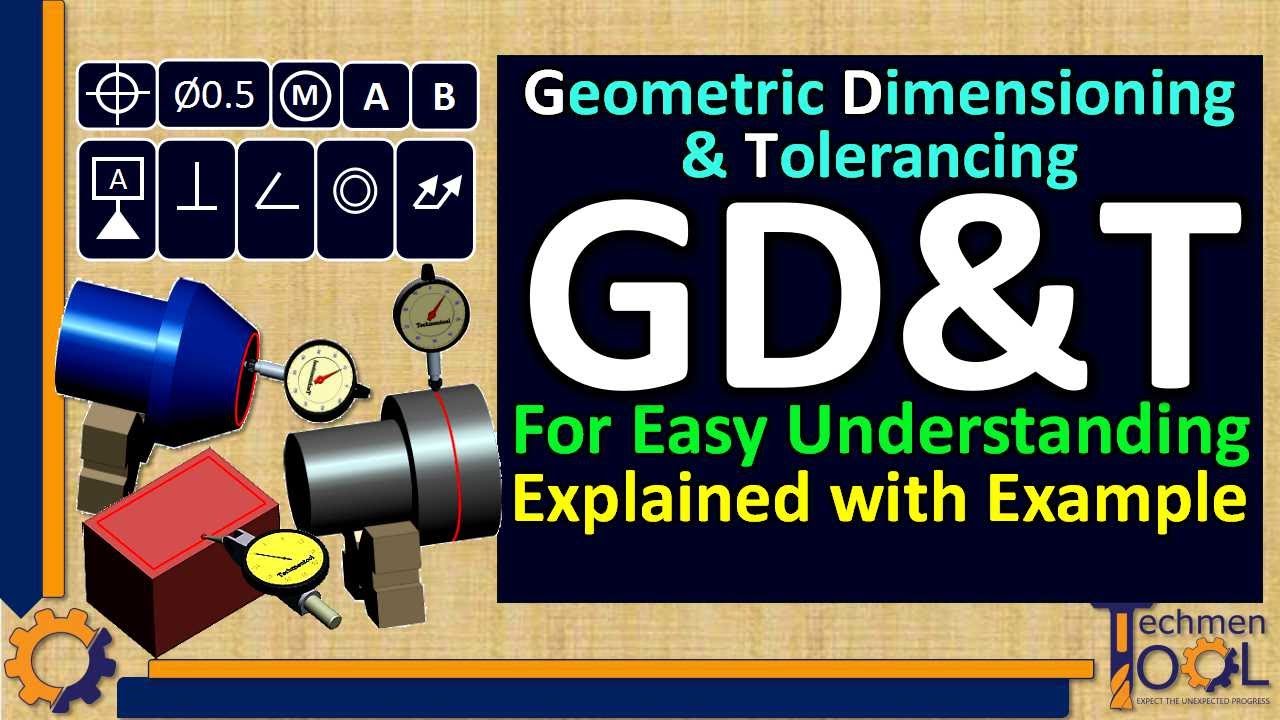
What is GD&T? | GD&T symbols Explained with Example | for Beginners Understanding | Subscribe Us
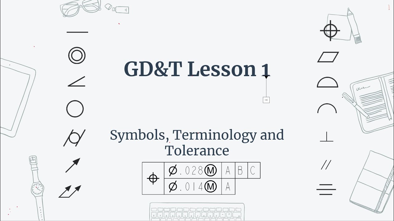
Understanding Engineering Drawings
Teknik Gambar Manufaktur XI Toleransi dan Suaian
Classes | Godot GDScript Tutorial | Ep 15
Dictionaries | Godot GDScript Tutorial | Ep 12
Tolerances Explained in CNC Machining (Defining for production)
5.0 / 5 (0 votes)